Ford Mustang (1999-2004) Service Manual: Exhaust Manifold to Exhaust Gas Recirculation (EGR) Valve Tube
Removal and Installation
NOTE: 3.8L shown, 4.6L (2V) similar.
1. With the vehicle in NEUTRAL, position it on a hoist.
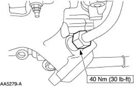
2. Disconnect the exhaust gas recirculation (EGR) valve tube from the exhaust manifold.
3. Remove the differential feedback exhaust gas recirculation (EGR) system vacuum hoses and the bracket bolts. Position the bracket assembly aside.
4. Disconnect the EGR tube from the EGR valve.
5. Remove the exhaust manifold-to-EGR valve tube.
6. To install, reverse the removal procedure.
 Exhaust Gas Recirculation (EGR) Valve - Mach I
Removal and Installation
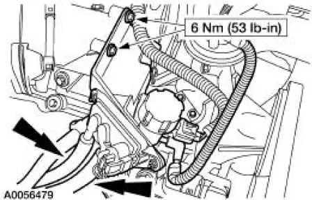
1. Remove the air intake scoop. For additional information, refer to
Section.
2. Remove the exhaust gas recirculation (EGR) valve.
1. Disconnect the EGR tube upper fi ...
 Exhaust Manifold to Exhaust Gas Recirculation (EGR)
Valve Tube - Cobra
Exhaust Manifold to Exhaust Gas Recirculation (EGR)
Valve Tube - Cobra
Removal and Installation
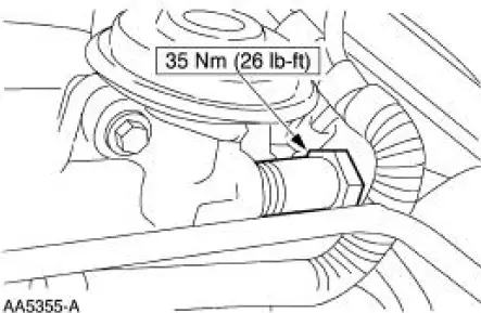
1. Remove the EGR valve. For addditional information, refer to Exhaust
Gas Recirculation (EGR)
Valve-Cobra in this section.
2. With the vehicle in NEUTRAL, position it on ...
Other materials:
Camshaft Runout
Special Tool(s)
Dial Indicator Gauge with
Holding Fixture
100-002 (TOOL-4201-C) or
equivalent
1. NOTE: Camshaft journals must be within specifications before
checking runout.
Use a Dial Indicator Gauge with Holding Fixture to measure the ...
Compressor to Condenser Discharge Line - 4.6L
Material
Item
Specification
PAG Refrigerant Compressor
Oil (R-134a Systems)
F7AZ-19589-DA (Motorcraft YN-
12-C)
WSH-M1C231-
B
Removal and Installation
NOTE: Installation of a new suction accumulator is not required when
repairing the ...
Transmission (Assembly)
Special Tool(s)
Dial Indicator Gauge with
Holding Fixture
100-002 (TOOL-4201-C) or
equivalent
Holding Fixture, Transmission
307-003 (T57L-500-B)
Remover/Installer, Bearing
Tube
308-024 (T75L-7025-B)
Re ...
