Ford Mustang (1999-2004) Service Manual: Speed Control (Diagnosis and Testing)
Refer to Wiring Diagrams Cell 31 , Speed Control for schematic and connector information.
Special Tool(s)
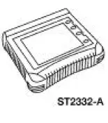 |
Worldwide Diagnostic System (WDS) 418-F224, New Generation STAR (NGS) Tester 418-F052, or equivalent diagnostic tool |
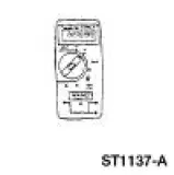 |
73 Digital Multimeter or equivalent 105-R0051 |
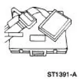 |
Breakout Box, EEC-V Control System 418-049, or equivalent 014-00950 |
 Speed Control
Torque Specifications
Speed Control
The speed control system consists of the following components:
speed control actuator cable (9A825)
deactivator switch
output shaft sensor (OSS)
speed control ...
 Principles of Operation
The speed control system is designed to maintain vehicle speed above 48 km/h
(30 mph). After the
ON switch is depressed, depressing the SET/ACCEL switch will activate the speed
control servo. To
inc ...
Other materials:
Geartrain
Power is transmitted from the torque converter to the Ravigneaux
geartrain components through the
input shaft and forward clutch cylinder.
The geartrain contains a Ravigneaux planetary set connected by
dual pinion gears.
By holding or driving ...
Transmission (Disassembly)
Special Tool(s)
Bearing Puller
205-D064 (D84L-1123-A) or
Equivalent
Front Hub Tool
204-069 (T81P-1104-C)
Holding Fixture
307-003 (T57L-500-B)
Impact Slide Hammer
100-001 (T50T-100-A)
Puller
...
Head restraints
WARNING: To minimize the risk of neck injury in the event of a
crash, the driver and passenger occupants should not sit in or
operate the vehicle, until the head restraint is placed in its proper
position. The driver should never adjust the head restraint whil ...
