
Ford Mustang (1999-2004) Service Manual: Throttle Position (TP) Sensor
Removal
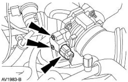
NOTE: The 3.8L engine is shown; the 4.6L (2V) is similar.
1. Disconnect the battery ground cable. For additional information, refer to Section.
2. Remove the throttle position (TP) sensor.
- Disconnect the connector.
- Remove the screws, and remove the sensor.
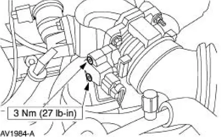
Installation
1. To install, reverse the removal procedure.
Throttle Position (TP) Sensor -Cobra
Removal and Installation
1. Disconnect the throttle position (TP) sensor electrical connector.
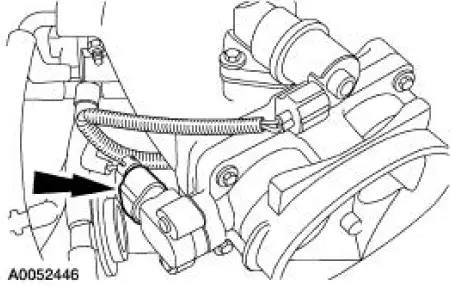
2. Remove the bolts and the TP sensor.
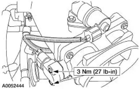
3. To install, reverse the removal procedure.
Throttle Position (TP) Sensor -Mach I
Removal and Installation
1. Remove the air intake scoop bracket. For additional information, refer to Section.
2. Disconnect the throttle position (TP) sensor electrical connector.
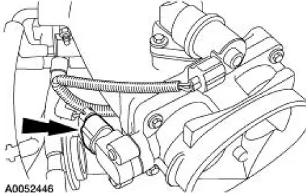
3. Remove the bolts and the TP sensor.
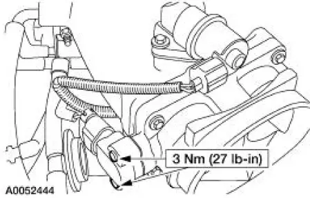
4. To install, reverse the removal procedure.
 Powertrain Control Module (PCM)
Removal
1. Disconnect the battery ground cable. For additional information,
refer to Section.
2. Remove the RH front door scuff plate.
3. Remove the RH cowl side trim panel.
Remove the ...
 Idle Air Control (IAC) Valve - 3.8L
Removal
1. Disconnect the battery ground cable. For additional information,
refer to Section.
2. NOTE: Discard the idle air control (IAC) valve gasket.
Remove the IAC valve.
Disconnec ...
Other materials:
Sensor Indicator - Rear
Special Tool(s)
Pinion Bearing Cone Remover
205-D002 (D79P-4621A)
Axle Bearing/Seal Plate
205-090 (T75L-1165-B)
Sensing Ring Replacer
206-041 (T89P-20202-A)
Removal
1. Remove the rear axle shaft bearing.
2. Using the special ...
Disassembly
1. Remove the driveshaft (4602). For additional information, refer to
Driveshaft in this section.
2. CAUTION: Under no circumstances is the driveshaft assembly to be
clamped in the
jaws of a vise or similar holding fixture. Denting or localizing fracture ca ...
Pinpoint Tests
CAUTION: Before removing and installing the GEM or its connectors,
disconnect the
battery. Failure to follow this caution will result in the GEM storing many
erroneous DTCs and it
may exhibit erratic operation after installation.
CAUTION: Be careful when pr ...
