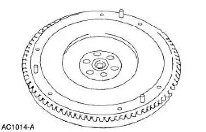
Ford Mustang (1999-2004) Service Manual: Flywheel Ring Gear
Removal
1. Remove the flywheel.
2. WARNING: This procedure should be carried out only by a correctly equipped and experienced acetylene torch operator. Tongs must be used or asbestos gloves worn when handling the heated flywheel ring gear. Failure to follow these instructions can result in personal injury.
CAUTION: Tap the flywheel ring gear evenly to prevent binding.
Remove the flywheel ring gear from the flywheel.
- Evenly heat the flywheel ring gear with an acetylene torch and use a brass drift to drive the flywheel ring gear off the flywheel.
Installation
1. WARNING: This procedure should be carried out only by a properly equipped and experienced acetylene torch operator. Tongs must be used or asbestos gloves worn when handling the heated flywheel ring gear. Failure to follow these instructions can result in personal injury.
CAUTION: Do not heat the flywheel ring gear beyond 261C (500F). Use heatindicating crayons to prevent overheating.
CAUTION: Keep the torch moving to prevent hot spots.
Evenly heat the flywheel ring gear with an acetylene torch.
- Install the flywheel ring gear with the bevel on the flywheel ring gear facing the rear of the flywheel.
- Use a brass drift to tap the flywheel ring gear into position, reheat as necessary.
2. Install the flywheel.
 Pilot Bearing
Special Tool(s)
Puller with Slide Hammer
308-001 (T58L-101-B)
1. Remove the clutch disc and the clutch pressure plate. For additional
information, refer to Disc
and Pressure Plate-3.8 ...
 Clutch Controls
General Specifications
Torque Specifications
...
Other materials:
Fuel System (Description and Operation)
Component Location
WARNING: Do not smoke or carry lighted tobacco or open flame of any
type when
working on or near any fuel-related components. Highly flammable mixtures are
always present
and may be ignited, resulting in possible personal injury ...
Temporary mobility kit
Note: The temporary mobility kit sealant compound in the canister is
to
be used for one tire only. See your Ford authorized dealer for additional
replacement sealant canisters.
The kit is located in the spare tire well in the trunk. The kit consists of
an ai ...
Transmission Description (Description and Operation)
The 4R70W has the following features:
Wide ratio gears
Four speeds
Rear wheel drive
Automatic
Electronic shift
Torque converter clutch control
Line pressure controls
The transmission uses Ravigneaux-style double-pinion gearset with ...
