Ford Mustang (1999-2004) Service Manual: Fuel Charging and Controls
The fuel injection supply manifold (9F792):
- delivers fuel to the fuel injector.
- receives fuel from the fuel supply line.
The throttle body:
- controls air supply to the upper intake manifold by positioning the throttle plate.
- connects the accelerator cable and, if equipped, the speed control actuator cable to the throttle lever.
- is not adjustable.
- cannot be cleaned.
The fuel injector:
- is electrically operated by the powertrain control module (PCM).
- has an internal solenoid that opens a needle valve to inject fuel into the lower intake manifold.
- atomizes the fuel as the fuel is delivered.
- is deposit-resistant. Do not clean.
The fuel pressure relief valve:
- is used to inspect and relieve fuel pressure.
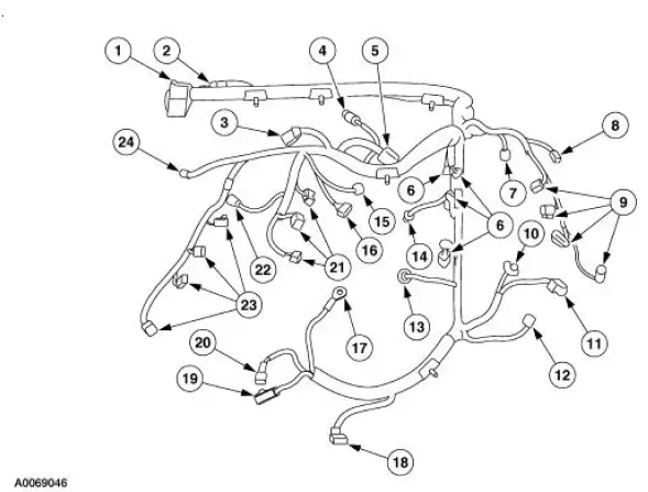
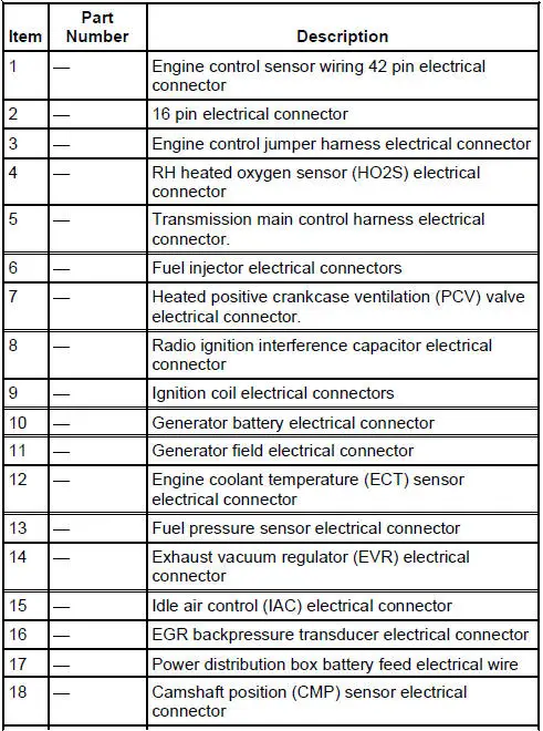
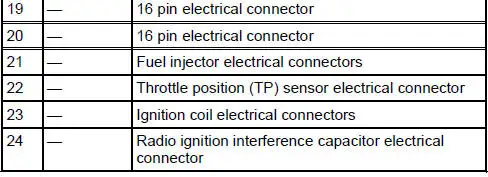
Fuel Charging Wiring Connections
Fuel Charging and Controls
Refer to the Powertrain Control/Emissions Diagnosis (PC/ED) manual.
Idle Speed Adjustment
Powertrain Control/Emissions Diagnosis (PC/ED) manual
 Fuel Charging and Controls - Mach I 4.6L (4V)
General Specifications
Torque Specifications
...
 Throttle Body
Removal
WARNING: Do not smoke or carry lighted tobacco or open flame of any
type when
working on or near any fuel related components. Highly flammable mixtures are
always present
and can ignite. Fai ...
Other materials:
Vehicle identification number
The vehicle identification number
is located on the driver’s side
instrument panel.
Please note that in the graphic,
XXXX is representative of your
vehicle identification number.
The Vehicle Identification Number (VIN) contains the following
information:
...
Diagnostic Instructions - Air Bag Supplemental Restraint
System (SRS)
Special Tool(s)
Worldwide Diagnostic System
(WDS)
418-F224,
New Generation STAR (NGS)
Tester
418-F052, or equivalent scan
tool
The symptom chart can be used to help locate the air bag supplemental
restraint system (SRS)
concerns if n ...
Temporary mobility kit
Note: The temporary mobility kit sealant compound in the canister is
to
be used for one tire only. See your Ford authorized dealer for additional
replacement sealant canisters.
The kit is located in the spare tire well in the trunk. The kit consists of
an ai ...
