Ford Mustang (1999-2004) Service Manual: Headliner
Removal
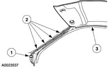
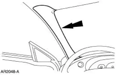
1. Remove the two upper quarter panels. For additional information, refer to Trim Panel-Upper Quarter in this section.
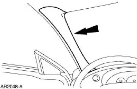
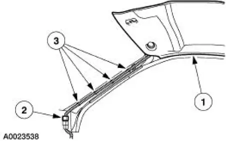
2. Remove the two windshield side garnish mouldings.
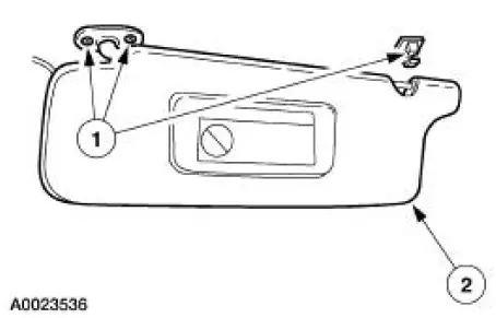
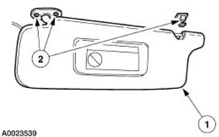
3. Remove the two sun visors.
1. Remove the six screws.
2. Position the sun visors aside.
- If equipped, disconnect the electrical connectors.
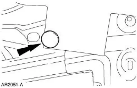
4. Remove the two pin-type retainers.
5. CAUTION: Folding the headliner will result in damage to the headliner.
Remove the headliner.
1. Disconnect the electrical connector.
2. Release the wiring harness locators.
3. Remove the headliner.
Installation
1. CAUTION: Folding the headliner will result in damage to the headliner.
Install the headliner.
1. Position the headliner.
- Apply Headliner Adhesive F1VY-19562-A meeting Ford specification WSSM2G355- B, to the headliner using the existing pattern.
2. Connect the electrical connector.
3. Engage the wiring harness locators.
2. Install the two pin-type retainers.

3. Install the two sun visors.
1. Position the sun visors.
- If equipped, connect the electrical connectors.
2. Install the screws.
4. Install the two windshield side garnish mouldings.
5. Install the two upper quarter trim panels. For additional information, refer to Trim Panel-Upper Quarter in this section.
 Trim Panel - Package Tray
Special Tool(s)
Torx Bit, Safety Belt Bolt
501-010 (T77L-2100-A)
Removal and Installation
1. Remove the screw and the coat hook.
2. NOTE: Inspect the shoulder safety belt guide cov ...
 Exterior Trim and Ornamentation
Torque Specifications
Exterior Trim and Ornamentation
The exterior trim and ornamentation consists of the following
components:
body side scoop
hood scoop (if equipped)
front spoiler ...
Other materials:
Disassembly
1. Remove the differential assembly from the differential housing. For
additional information, refer
to Differential Case in this section.
2. Remove the bolts.
3. CAUTION: Do not damage the threads in the bolt holes.
Insert a punch in the bolt holes and d ...
Torque Converter Leak Check
Special Tool(s)
Leak Tester, Torque Converter
307-421
1. Clean the outside surface of the torque converter.
2. Install the special tool into the converter hub.
3. WARNING: Always follow correct safety procedures while using press.
Failure t ...
Exhaust Manifold - Inspection
Special Tool(s)
Straight Edge
303-D039 (D83L-4201-A) or
equivalent
1. Place a straight edge across the exhaust manifold flanges and check for
warping with a feeler
gauge.
Bearing -Inspection
1. Inspect bearings for the following defects. P ...
