Ford Mustang (1999-2004) Service Manual: Cylinder Block Core Plug Replacement
Special Tool(s)
|
|
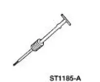
Slide Hammer 100-001 (T50T-100-A) |
Material

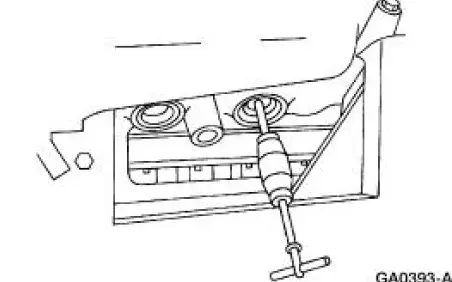
1. Use a slide hammer or tools suitable to remove the cylinder block core plug.
2. Inspect the cylinder block plug bore for any damage that would interfere with the correct sealing of the plug. If the cylinder block plug bore is damaged, bore for the next oversize plug.
3. NOTE: Oversize plugs are identified by the OS stamped in the flat located on the cup side of the plug.
Coat the cylinder block core plug and bore lightly with Threadlock 262 and install the cylinder block core plug.
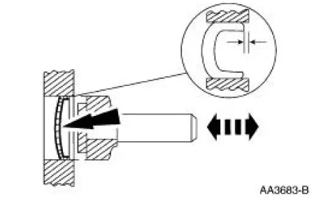
Cup-Type
4. CAUTION: Use care during this procedure so as not to disturb or distort the cup sealing surface.
CAUTION: When installed, the flanged edge must be below the chamfered edge of the bore to effectively seal the bore.
Use a tool suitable to seat the cup-type cylinder block core plug.
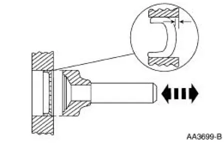
Expansion-Type
1. CAUTION: Do not contact the crown when installing an expansion-type cylinder block core plug. This could expand the plug before seating and result in leakage.
Use tool suitable to seat the expansion-type cylinder block core plug.
Spark Plug Hole Thread Repair
1. There is no authorized repair for spark plug hole threads. If the threads are damaged, install a new cylinder head.
 Cylinder Head - Distortion
Special Tool(s)
Straight Edge
303-D039 (D83L-4201-A) or
equivalent
1. Use a straight edge and a feeler gauge to inspect the cylinder head for
flatness. If the cylinder
head is disto ...
 Spark Plug - Inspection
1. Inspect the spark plug for a bridged gap.
Check for deposit build-up closing the gap between the electrodes.
Deposits are caused
by oil or carbon fouling.
Clean the spark plug.
2. Ch ...
Other materials:
Removal
1. Remove the differential housing cover (4033) and drain the rear axle
(4001). For additional
information, refer to Differential Housing Cover in this section.
2. CAUTION: Reinstall the differential pinion shaft (4211) and the bolt in
the differential
case ...
Supercharger Cooling System Flushing
1. WARNING: Never remove the pressure relief cap while the engine is
operating or
when the cooling system is hot. Failure to follow these instructions can result
in damage
to the cooling system or engine or personal injury. To avoid having scalding hot
cool ...
Removal
Convertible
1. For removal of the back window glass, refer to Section.
Coupe
WARNING: To prevent glass splinters from entering eyes or
cutting hands, wear safety
glasses and heavy gloves when cutting glass from the vehicle.
2. Remove the roof side ...
