Ford Mustang (1999-2004) Service Manual: Hydraulic Control Unit
Removal
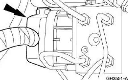
1. Disconnect the battery ground cable(14301).
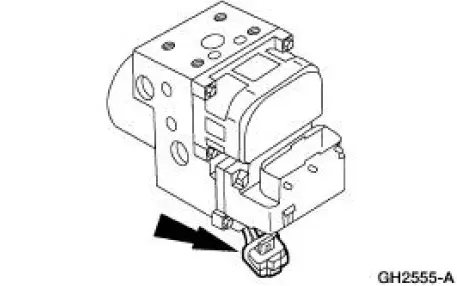
2. Disconnect the anti-lock-brake control module electrical connector.
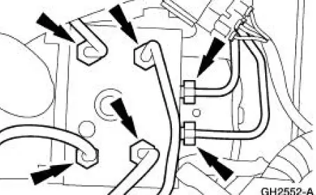
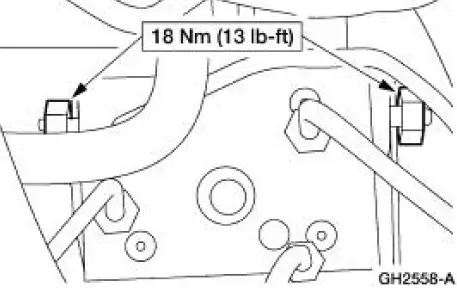
3. NOTE: The 4 wheel anti-lock brake system (4WABS) with traction control is shown , the 4WABS without traction control system is similar with one less hydraulic line.
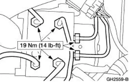
NOTE: Plug brake lines to prevent any brake fluid loss.
Disconnect the brake lines from the hydraulic control unit (HCU).
4. Remove the HCU bracket nuts to HCU.
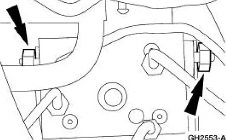
5. Remove the HCU.
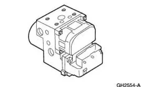
6. Remove the pump motor electrical connector.
7. Remove the anti-lock-brake control module screws.
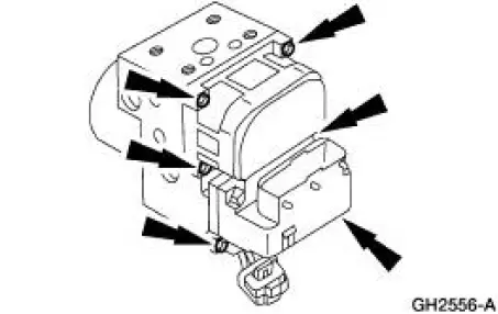
8. Remove the anti-lock-brake control module from the HCU.
Installation
1. NOTE: The brake system must be bled after the HCU is installed or replaced. To install, reverse the removal procedure.
 Sensor Indicator - Rear
Special Tool(s)
Pinion Bearing Cone Remover
205-D002 (D79P-4621A)
Axle Bearing/Seal Plate
205-090 (T75L-1165-B)
Sensing Ring Replacer
206-041 (T89P-20202-A)
Removal
...
 Module
Removal
1. Remove the hydraulic control unit (HCU). Refer to Hydraulic Control Unit .
2. Remove the pump motor electrical connector.
3. Remove the anti-lock-brake control module screws.
4. Remove th ...
Other materials:
Transmission (Removal)
1. Remove the gearshift lever knob.
2. Remove the console panel gearshift plate. Disconnect the cigar lighter
electrical connector, then
lift the gearshift lever boot over the gearshift lever.
3. Remove the bolts and the upper gearshift lever.
4. Remove ...
Vehicle identification number
The vehicle identification number
is located on the driver’s side
instrument panel.
Please note that in the graphic,
XXXX is representative of your
vehicle identification number.
The Vehicle Identification Number (VIN) contains the following
information:
...
Air Bag Supplemental Restraint System (SRS) (Diagnosis and Testing)
Refer to Wiring Diagrams Cell 46 , Air Bag for schematic and connector
information.
Special Tool(s)
Diagnostic Tool, Restraint
System
418-F088 (105-R0012)
Restraint System Diagnostic Tool Warning
WARNING: This tool is for restraint system se ...
