
Ford Mustang (1999-2004) Service Manual: Module
Removal
1. Remove the hydraulic control unit (HCU). Refer to Hydraulic Control Unit .
2. Remove the pump motor electrical connector.
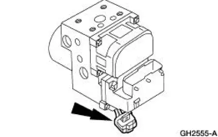
3. Remove the anti-lock-brake control module screws.
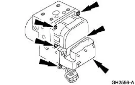
4. Remove the anti-lock-brake control module from the HCU.
Installation
1. NOTE: The brake system must be bled after the HCU is installed or replaced.
To install, reverse the removal procedure.
 Hydraulic Control Unit
Removal
1. Disconnect the battery ground cable(14301).
2. Disconnect the anti-lock-brake control module electrical connector.
3. NOTE: The 4 wheel anti-lock brake system (4WABS) with traction
cont ...
 Sensor - Front
Removal
1. Remove the wheel and tire assembly.
2. Remove the inner fender splash shield.
1. Remove the inner fender splash shield push pins.
2. Remove the inner fender splash shield screw.
3. R ...
Other materials:
Negative and Positive Camber
Camber is the vertical tilt of the wheel (1007) when viewed from the front.
Camber can be positive or
negative and has a direct effect on tire wear.
Caster
Item
Part Number
Description
1
-
Positive caster
2
-
True vertical
...
Windshield washers
Note: Do not operate the wipers on a dry windshield. This may scratch
the glass, damage the wiper blades or cause the wiper motor to burn out.
Always use the windshield washer before wiping a dry windshield.
Note: Do not operate the washer when the washer re ...
Suspension System - General Information
Alignment Specifications
General Specifications
Torque Specifications
Description
Nm
lb-ft
Front suspension camber adjustment plate bolt
40
30
Front suspension camber adjustment plate nuts
40
30
Rear camber adjustment nut ...
