Ford Mustang (1999-2004) Service Manual: Ignition Coil
Material
| Item | Specification |
| Silicone Brake Caliper Grease and Dielectric Compound D7AZ-19A331-A or equivalent | ESE-M1C171- A |
Removal and Installation
1. Disconnect the battery ground cable (14301). For additional information, refer to Section.
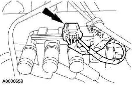
2. Disconnect the ignition coil electrical connector.
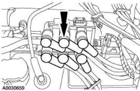
3. CAUTION: Spark plug wires (12286) must be connected to the correct ignition coil terminal. Mark spark plug wire locations before removing them.
Twist while pulling upward to disconnect the spark plug wires.
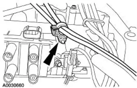
4. Disconnect the accelerator cable retaining clamp from the ignition coil stud bolt.
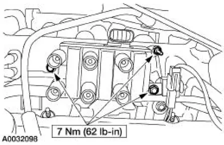
5. Remove the bolts and the ignition coil (12029).
6. NOTE: Apply silicone brake caliper grease and dielectric compound to the inside of the spark plug wire coil boot.
NOTE: Be sure to reinstall the radio ignition interference capacitor (18801) under the correct mounting bolt.
To install, reverse the removal procedure.
 Engine Ignition (Description and Operation)
The ignition coil (12029), which is mounted on the upper intake manifold, can
be described as a coil
pack containing three separate coil units. Each coil unit is individually
controlled by the power ...
 Spark Plug Wire
Special Tool(s)
Remover, Spark Plug Wire
303-106 (T74P-6666A)
Material
Item
Specification
Silicone Brake Caliper Grease
and Dielectric Compound
D7AZ-19A331-A or equiva ...
Other materials:
Fuel Vapor Control Tube Assembly Valve
Removal and Installation
1. Remove the fuel tank. For additional information, refer to
Section.
2. Remove the retainers.
3. NOTE: The fuel vapor vent valve, fuel vapor control valve and the
in-line fuel tank pressure
sensor are repaired as a fuel va ...
Power windows
WARNING: Do not leave children unattended in your vehicle
and do not let children play with the power windows. They may
seriously injure themselves.
WARNING: When closing the power windows, you should verify
they are free of obstructions and make sure that chi ...
Air Cleaner Element - 4.6L (2V)
Removal and Installation
1. Remove the air cleaner outlet tube (9B659). For additional
information, refer to Air Cleaner
Outlet Pipe-4.6L (2V) in this section.
2. Remove the mass air flow (MAF) assembly.
1. Release the clip.
2. Remove the MAF sens ...
