
Ford Mustang (1999-2004) Service Manual: Bypass Tube - Cobra
Material
| Item | Specification |
| Motorcraft Premium Gold Engine Coolant VC-7-A (in Oregon VC-7-B) (yellow color) | WSS-M97B51- A1 |
Removal and Installation
1. Drain the engine coolant. For additional information, refer to Cooling System Draining, Filling and Bleeding in this section.
2. Disconnect the radiator upper hose and the radiator lower hose.
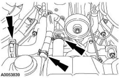
3. Remove the supercharger belt. For additional information, refer to Section.
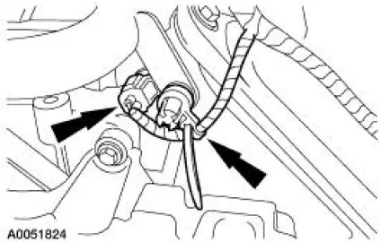
4. Disconnect the engine coolant temperature sensor electrical connector and unclip the wiring harness from the stud.
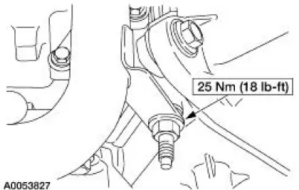
5. NOTE: LH is shown, RH is similar.
Remove the coolant bypass nuts.
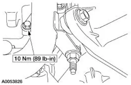
6. NOTE: LH is shown, RH is similar.
Remove the bolts and the coolant bypass tube.
7. NOTE: Install new bypass tube O-rings and lubricate them, using premium engine coolant.
To install, reverse the removal procedure.
8. Fill and bleed the engine cooling system. For additional information, refer to Cooling System Draining, Filling and Bleeding in this section.
 Bypass Tube - 3.8L
Material
Item
Specification
Motorcraft Premium Gold
Engine Coolant
VC-7-A (in Oregon VC-7-B)
(yellow color)
WSS-M97B51-
A1
Removal and Installation
1. Drain the engine coola ...
 Bypass Tube - Mach I
Material
Item
Specification
Motorcraft Premium Gold
Engine Coolant
VC-7-A (in Oregon VC-7-B)
(yellow color)
WSS-M97B51-
A1
Removal and Installation
1. Remove the air intake ...
Other materials:
Material
Item
Specification
Threadlock and
Sealer
E0AZ-19554-AA
WSK-M2G351-A5 (type
II)
Shoulder Bolt Kit
F5ZZ-76539A04-A
-
NOTE: Before starting the adjustment process, inspect the top for damage,
make sure that the door
window glass ...
Manual Transaxle/Transmission - TR3650
General Specifications
Torque Specifications
...
The better business bureau (BBB) auto line program
(U.S. Only)
Your satisfaction is important to Ford Motor Company and to your dealer.
If a warranty concern has not been resolved using the three-step
procedure outlined earlier in this chapter in the Getting the Services
You Need section, you may be eligible to participa ...
