Ford Mustang (1999-2004) Service Manual: Input Shaft and Bearing
Special Tool(s)
 |
Remover, Driver Pinion Bearing Cone 205-D002 (D79L-4621-A) or equivalent |
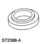 |
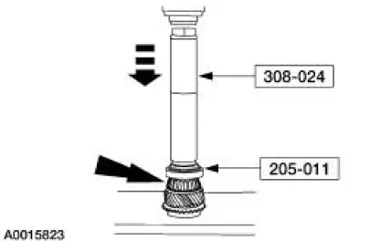
Installer, Drive Pinion Bearing Cone 205-011 (T57L-4621-B) |
 |
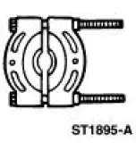
Remover/Installer, Bearing Tube 308-024 (T75L-7025-B) |
Disassembly and Assembly
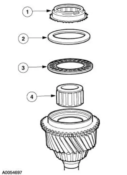
1. Disassemble the input shaft.
1. Remove the third/fourth synchronizer blocking ring.
2. Remove the input shaft thrust washer.
3. Remove the input shaft thrust bearing.
4. Remove the input shaft pocket bearing.
- Inspect all components for wear or damage. Install new components as necessary.
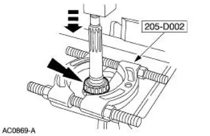
2. Using the special tool and a press, remove the input shaft front bearing assembly. Discard the bearing.
3. Inspect the input shaft and bearings for wear or damage. Install new components as necessary.
4. Using the special tools and a press, install the new input shaft front bearing.
5. Install the input shaft pocket bearing, the washer, input shaft bearing and the third/fourth synchronizer blocking ring.
- Lubricate the bearing and bearing race with petroleum jelly.
 Transmission (Disassembly)
Special Tool(s)
Remover, Mainshaft Bearing
308-058 (T77J-7025-H)
Screw, Bearing Removal tube
308-092 (T84T-7025-B)
Holding Fixture, Transmission
307-003 (T57L- ...
 Output Shaft
Special Tool(s)
Remover, Drive Pinion Bearing
Cone
205-D002 (D79L-4621-A) or
equivalent
Installer, Drive Pinion Bearing
Cone
205-011 (T57L-4621-B)
...
Other materials:
External Controls (Description and Operation)
The transmission shift cable transfers the transmission operating mode from
the gearshift lever to the
automatic transmission (7003). The indicated position of the transmission floor
mounted selector lever
is transferred to the transmission through the cable ...
Manual Transmission
The TR3650 five-speed manual transmission features the following:
The fifth speed gear functions as an overdrive gear.
The forward gears are synchronized and helical cut.
The reverse gear operates through a constant-mesh, fully
synchronized system.
...
Fuel Filter
Removal
WARNING: Fuel supply lines on all vehicles equipped with fuel injected
engines will
remain pressurized for long periods of time after engine shutdown. Fuel system
pressure must
be relieved prior to fuel system service to prevent possible personal inj ...
