Ford Mustang (1999-2004) Service Manual: Inspection and Verification
1. Verify the customer concern by operating the wiper/washer system.
2. Visually inspect for obvious signs of mechanical and electrical damage.
Visual Inspection Chart
| Mechanical | Electrical |
|
|
3. If the concern remains after the inspection, connect the diagnostic tool to the data link connector (DLC) located beneath the instrument panel and select the vehicle to be tested from the diagnostic tool menu. If diagnostic tool does not communicate with the vehicle:
- Check that the program card is correctly installed.
- Check the connections to the vehicle.
- Check the ignition switch position.
4. If diagnostic tool still does not communicate with the vehicle, refer to the diagnostic tool manual.
5. Carry out the DATA LINK DIAGNOSTIC TEST. If diagnostic tool responds with:
- CKT914, CKT915 or CKT70 = ALL ECUS NO RESP/NOT EQUIP, refer to Section.
- NO RESPONSE/NOT EQUIPPED for GEM, go to Pinpoint Test A.
- SYSTEM PASSED, retrieve and record the continuous diagnostic trouble codes (DTCs), erase the continuous DTCs and carry out self-test diagnostics for the GEM.
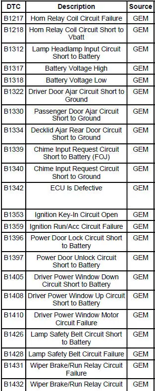
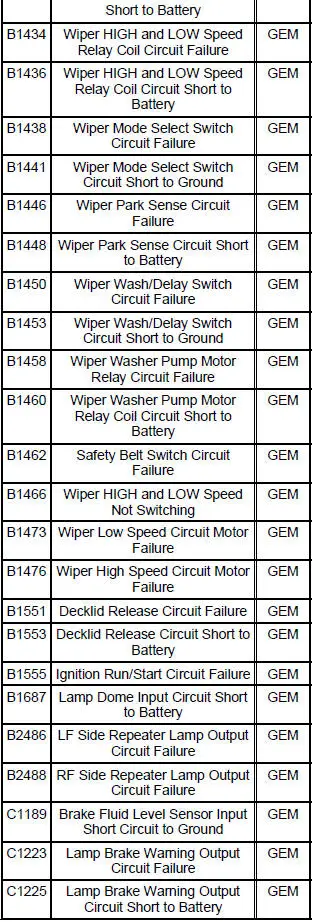
6. If the DTCs retrieved are related to the concern, go to GEM Diagnostic Trouble Code (DTC) Index to continue diagnostics.
7. If no DTCs related to the concern are retrieved, proceed to Symptom Chart to continue diagnostics.
GEM Diagnostic Trouble Code (DTC) Index
Symptom Chart
| Condition | Possible Sources | Action |
|
|
|
|
|
|
|
|
|
|
|
|
|
|
|
|
|
|
|
|
|
 Principles of Operation
Multifunction Wipers
The front wiper/washer feature controls the speed of the front
windshield wipers and the amount of
washer fluid sprayed on the front windshield when requested by the
cus ...
 Pinpoint Tests
CAUTION: Before removing and installing the GEM or its connectors,
disconnect the
battery. Failure to follow this caution will result in the GEM storing many
erroneous DTCs and it
may exhibit errati ...
Other materials:
Accessory Drive Belt Idler Pulley - 4.6L (2V) and (4V)
Removal and Installation
Mach I
1. Remove the air intake scoop. For additional information, refer to Section.
Cobra
2. Remove the supercharger drive belt cover.
3. Rotate the supercharger belt tensioner clockwise and remove the
supercharger belt.
4. Remov ...
Valve Springs
Special Tool(s)
Compressor, Valve Spring
303-163 (T81P-6513-A)
Material
Removal
1. Remove the LH and the RH valve covers. For additional information,
refer to Valve Cover-LH
and Valve Cover RH in this section.
2. Rotate the crankshaft un ...
Air Cleaner - 4.6L (2V) and 4.6L (4V)
Removal and Installation
Mach I
1. Disconnect the air intake scoop outlet tube.
All vehicles
2. Remove the air cleaner outlet tube from the throttle body. For
additional information, refer to Air
Cleaner Outlet Pipe-4.6L (2V) or Air Cleaner Outlet Pipe- ...
