Ford Mustang (1999-2004) Service Manual: Vacuum Hose Repair - Mini-Tube
Special Tool(s)
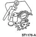 |
Vacuum Pump Kit 416-D002 (D95L-7559-A) or equivalent |
1. Measure the length of the damaged area of the mini-tube vacuum hose.
2. Cut a piece of standard 1/8 inch inner diameter vacuum hose approximately 25 mm (1 inch longer than the damaged area of the mini-tube vacuum hose).
3. Cut off the mini-tube vacuum hose on each side of the damaged area.
4. WARNING: Read the warning information on the product label to prevent possible personal injury.
Dip the mini-tube hose ends in commercially available paint thinner containing methyl ethyl ketone (MEK). This solvent will seal the mini-tube in the vacuum hose.
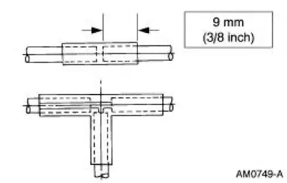
5. Insert the ends of the mini-tube vacuum hose approximately 9 mm (3/8 inch) into the ends of the standard 1/8 inch repair vacuum hose section.
6. Shake the repair joint after assembly to make sure the solvent is dispersed and the vacuum line is not plugged.
7. Test the system for a vacuum leak in the repair area.
- Use the Vacuum Tester or equivalent.
 Contaminated Refrigerant Handling
1. CAUTION: If contaminated refrigerant is detected, DO NOT recover the
refrigerant
into your recovery/recycling equipment.
Recover the contaminated refrigerant using suitable recovery-only equipment ...
 Air Distribution and Filtering
Torque Specifications
...
Other materials:
Brake Caliper - Cobra
Removal
1. Raise and support the vehicle.
2. Remove the tire and wheel assembly.
3. Remove the caliper locating pin E-clip.
4. Remove the caliper locating pin.
5. Remove the front brake flow bolt.
6. Remove the caliper.
7. Remove the brake pa ...
Air Conditioning (A/C) System Recovery, Evacuation and Charging
Special Tool(s)
R-134a A/C Refrigerant Center
176-00002 or equivalent
R-134a A/C Refrigerant Center
023-00153 or equivalent
R-134a Manifold Gauge Set
176-R032A or equivalent
1.2 CFM Vacuum Pump
023-00162 o ...
Power windows
WARNING: Do not leave children unattended in your vehicle
and do not let children play with the power windows. They may
seriously injure themselves.
WARNING: When closing the power windows, you should verify
they are free of obstructions and make sure that chi ...
