Ford Mustang (1999-2004) Service Manual: Installation
NOTE: Do not use a fiber disc to clean the surfaces. Fibers from the disc can get into the oil pan and oil and clog the oil bypass valve.
1. Clean and inspect the cylinder head for flatness.
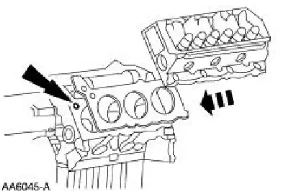
2. Install a new head gasket on the cylinder block with the small hole to the front of the engine.
3. Position the cylinder head.
4. CAUTION: Always use new bolts.
NOTE: Lubricate the bolts with clean engine oil.
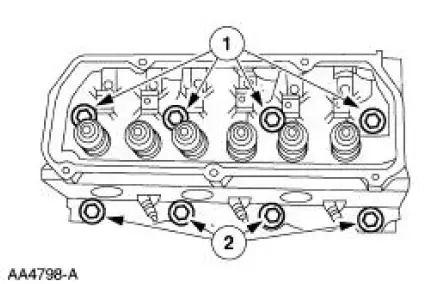
Install new bolts. Refer to the location note made during removal and make sure the bolts are installed the correct location.
1. Install the new long bolts.
2. Install the new short bolts.
5. Tighten the bolts in three stages in the sequence shown.
- Stage 1: Tighten the bolts to 20 Nm (15 lb-ft).
- Stage 2: Tighten the bolts to 40 Nm (30 lb-ft).
- Stage 3: Tighten the bolts to 50 Nm (37 lb-ft).
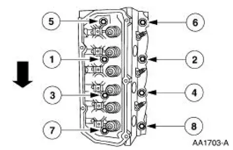
6. CAUTION: Do not loosen all of the bolts at one time. Each bolt must be loosened and final-tightened prior to working on the next bolt in the sequence.
NOTE: The short bolts are numbered 2, 4, 6 and 8 and the long bolts numbered 1, 3, 5 and 7.
Loosen, then tighten the bolts in two stages in the sequence shown.
- Stage 1: Tighten short bolts to 25 Nm (18 lb-ft), then tighten an additional 180 degrees.
- Stage 1: Tighten long bolts to 45 Nm (33 lb-ft), then tighten an additional 180 degrees.

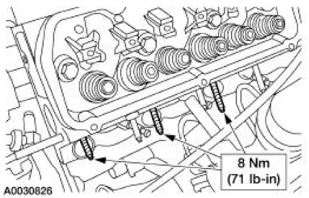
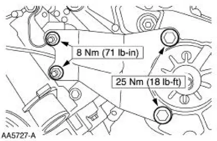
7. Install the exhaust manifold studs.
8. Install the bracket and bolts.
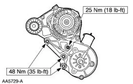
9. Install the support bracket.
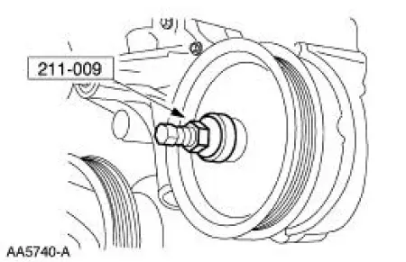
10. Using the special tool, install the power steering pump pulley.
11. Install the drive belt.
12. Install the push rods. For additional information, refer to Push Rod in this section.
13. Install the lower intake manifold. For additional information, refer to Lower Intake Manifold in this section.
14. Install the LH exhaust manifold. For additional information, refer to Exhaust Manifold-LH in this section.
15. Connect the battery ground cable.
16. CAUTION: Correct cooling system bleeding is critical for correct engine cooling.
Fill and bleed the engine cooling system.
 Removal
1. Disconnect the battery negative cable.
2. Drain the engine cooling system.
3. Remove the LH exhaust manifold. For additional information, refer to
Exhaust Manifold-LH in
this section.
4. ...
 Cylinder Head RH
Material
...
Other materials:
Ford Extended Service Plan
FORD ESP EXTENDED SERVICE PLANS
PROTECT YOURSELF FROM THE RISING COST OF VEHICLE REPAIRS
WITH A FORD EXTENDED SERVICE PLAN.
SERVICE PLANS (U.S. only)
More than 32 Million Ford and Lincoln owners have discovered the
powerful protection Ford ESP. It is the only ...
Diagnostic Strategy
Troubleshooting an electronically controlled automatic transmission
is simplified by using the proven
method of diagnosis. One of the most important things to remember is
that there is a definite
procedure to follow.
NOTE: Do not take any short cut ...
Removal
1. Remove the differential assembly from the differential housing. For
additional information, refer
to Differential Case in this section.
2. CAUTION: Record the torque necessary to maintain rotation of the drive
pinion gear
through several revolutions prio ...
