Ford Mustang (1999-2004) Service Manual: Installation
All vehicles
1. NOTE: If the valve cover is not secured within four minutes, the sealant must be removed and the sealing area cleaned with metal surface cleaner. Allow to dry until there is no sign of wetness, or four minutes, whichever is longer. Failure to follow this procedure can result in future oil leakage.
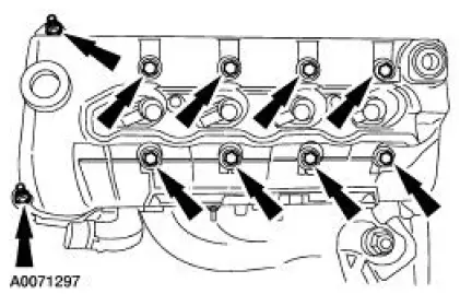
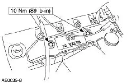
Apply silicone gasket and sealant to areas shown.
2. Install the LH valve cover and loosely install the bolts.
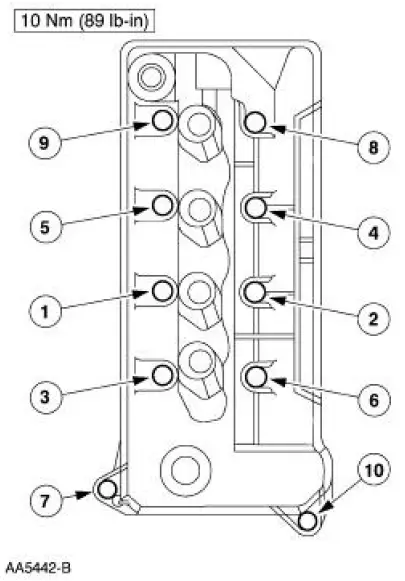
3. Tighten the LH valve cover bolts in the sequence shown.
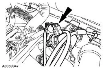
4. Connect the wiring harness anchor to the valve cover stud bolt.
5. Connect the positive crankcase ventilation (PCV) valve hose and electrical connector.
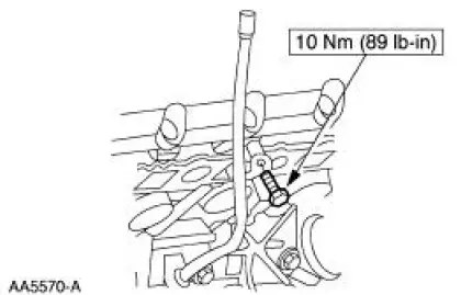
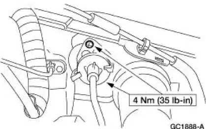
6. Position the oil level indicator tube and install the bolt.
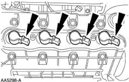
7. Install the LH ignition coils.
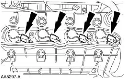
8. Connect the ignition coil electrical connectors.
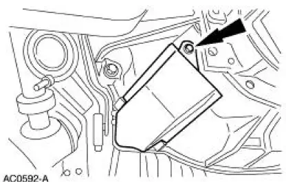
9. Install the LH ignition coil cover and the bolts.
Manual transmission vehicles
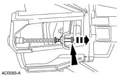
10. Install the clutch release cable and install the two screws.
11. Raise and support the vehicle. For additional information, refer to Section.
12. Connect the clutch release cable to the clutch release fork.
13. Install the dust shield and the screw.
14. Lower the vehicle.
All vehicles
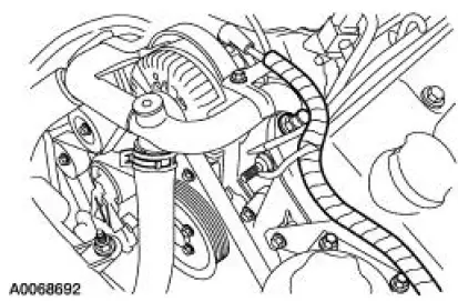
15. Install the Hydro-Boost brake booster. For additional information, refer to Section.
16. Install the air intake scoop. For additional information, refer to Section.
 Removal
All vehicles
1. Remove the air intake scoop. For additional information, refer to Section.
2. Remove the Hydro-Boost brake booster. For additional information, refer to
Section..
3. Raise and suppo ...
Other materials:
Key Programming - Program a Key Using Two
Programmed Keys
Special Tool(s)
Worldwide Diagnostic System
(WDS)
418-F224,
New Generation STAR (NGS)
Tester
418-F052, or equivalent
diagnostic tool
NOTE: This procedure only works if two or more programmed ignition keys are
available and it is
desi ...
Release Cable - Clutch
Removal
CAUTION: Whenever the clutch release lever cable (7K553) is
disconnected for any
reason, such as transmission removal, clutch pedal components or clutch
release lever cable
replacement, it is imperative the correct method for installing the clut ...
Caliper (DISASSEMBLY AND ASSEMBLY)
Disassembly
1. Remove the disc brake caliper (2B120). For additional information,
refer to Caliper in this
section.
2. Drain the remaining brake fluid from disc brake caliper.
3. Apply low air pressure to the fluid port in the disc brake caliper.
...
