Ford Mustang (1999-2004) Service Manual: Lamp Switch - Headlamp
Removal
1. Disconnect the battery ground cable.
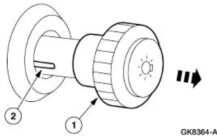
2. Remove the headlamp switch knob.
1. Pull the headlamp switch knob out.
2. Insert a thin tool into the slot, pull and remove the headlamp switch knob.
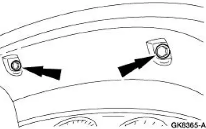
3. Remove the instrument panel cluster finish panel.
- Remove the screws and remove the finish panel.
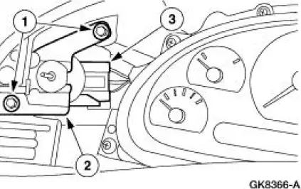
4. Remove the headlamp switch.
1. Remove the screws.
2. Remove the switch.
3. Disconnect the electrical connectors.
Installation
1. NOTE: When the battery is disconnected and reconnected, some abnormal drive symptoms may occur while the vehicle relearns its adaptive strategy. The vehicle may need to be driven 16 km (10 mi) or more to relearn the strategy.
To install, reverse the removal procedure.
 Lamp Assembly - Rear
Removal
1. Position the luggage compartment trim aside.
Remove the two retainers.
2. Remove the four rear lamp nuts.
3. Remove the rear lamp assembly, disconnect the electrical connectors an ...
 Lamp Switch - Brake Pedal Position (BPP)
Removal
1. Disconnect the battery ground cable.
2. Remove the brake pedal position (BPP) switch.
1. Remove the clip.
2. Remove the retainer.
3. Disconnect the electrical connector.
4. ...
Other materials:
Installation
1. CAUTION: Timing chain procedures must be followed exactly or damage
to the
pistons or valves will result.
Compress the tensioner plunger, using a soft-jawed vise.
2. Install a retaining clip on the tensioner to hold the plunger in during
installation.
...
Instrument Cluster (Diagnosis and Testing)
Refer to Wiring Diagrams Cell 60 , Instrument Cluster for schematic and
connector information.
Special Tool(s)
Worldwide Diagnostic System
(WDS)
418-F224,
New Generation STAR (NGS)
Tester
418-F052, or equivalent
diagnostic tool
...
Piston - Ring-to-Groove Clearance
1. Inspect the piston for ring land damage or accelerated wear.
2. Measure the piston ring-to-groove clearance.
Refer to the appropriate section in Group for the procedure.
If out of specification, install new components as necessary. Refer
to the a ...
