Ford Mustang (1999-2004) Service Manual: Pinpoint Test O: DTC B1870 - Air Bag Indicator Shorted to Battery
Normal Operation
The air bag indicator is designed to illuminate for 6 (+/-2) seconds when the ignition switch is turned to the RUN position. This initial 6 seconds of illumination is considered normal operation and is called proveout of the air bag indicator. The air bag indicator is then used to warn the driver that there is a fault in the air bag supplemental restraint system (SRS).
While the air bag indicator is lit, the restraints control module (RCM) monitors the air bag indicator for short to battery conditions. If the RCM detects a short to battery condition on the air bag indicator circuit, it will store a diagnostic trouble code (DTC) B1870 in memory.
If the RCM detects an air bag indicator failure in addition to another SRS failure, the RCM will send a signal to the generic electronic module (GEM) to produce five sets of five tone bursts.
Possible Causes
An air bag indicator short to battery condition can be caused by:
- damaged wiring on circuit 608 (BK/YE).
- an instrument cluster malfunction.
- an RCM internal concern.
PINPOINT TEST O: DTC B1870 - AIR BAG INDICATOR SHORTED TO BATTERY
| Test Step | Result / Action to Take |
| O1 CHECK FOR A HARD OR INTERMITTENT DTC | Yes This is a hard fault. The fault condition is still present. This fault cannot be cleared until it is corrected and the DTC is no longer retrieved during the ondemand self test. GO to O2 . No This is an intermittent fault. The fault condition is not present at this time. GO to O4 . |
|
|
| O2 CHECK THE AIR BAG INDICATOR CIRCUIT | Yes INSTALL a new RCM. GO to O5 . No GO to O3 . |
| WARNING: If the supplemental restraint system
(SRS) is
being serviced, the system must be deactivated and restraint
system diagnostic tools must be installed. Refer to Air Bag
Supplemental Restraint System (SRS) in this section.
The air bag restraint system diagnostic tools must be removed and the air bag modules reconnected when the system is reactivated to avoid non-deployment in a collision, resulting in possible personal injury. NOTE: Diagnostics or repairs are not to be performed on a seat equipped with a seat side air bag with the seat in the vehicle. Prior to attempting to diagnose or repair a seat concern when equipped with a seat side air bag, the seat must be removed from the vehicle and the restraint system diagnostic tools must be installed in the seat side air bag electrical connectors. The restraint system diagnostic tools must be removed prior to operating the vehicle over the road. NOTE: After diagnosing or repairing an SRS, the restraint system diagnostic tools must be removed before operating the vehicle over the road. NOTE: After diagnosing or repairing a seat system, the restraint system diagnostic tools must be removed before operating the vehicle over the road. NOTE: The SRS must be fully operational and free of faults before releasing the vehicle to the customer.
|
|
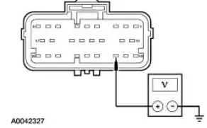
| O3 CHECK AIR BAG INDICATOR CIRCUIT FOR SHORT TO BATTERY | Yes REPAIR the instrument cluster. GO to O5 . No REPAIR the circuit. GO to O5 . |
|
|
| O4 CHECK FOR AN INTERMITTENT FAULT | Yes CHECK for causes of intermittent short to battery on circuit 608 (BK/YE). Attempt to recreate the hard fault by flexing the wire harness and cycling the ignition key frequently. REPAIR any intermittent concerns found. GO to O5 . No GO to O5 . |
|
|
| O5 CHECK FOR ADDITIONAL DTCs | Yes Do not clear any DTCs until all DTCs have been resolved. GO to the Restraints Control Module (RCM) Diagnostic Trouble Code (DTC) Priority Table in this section for pinpoint test direction. No RECONNECT the system. REACTIVATE the system. PROVE OUT the system. REFER to Air Bag Supplemental Restraint System (SRS) in this section. CLEAR all DTCs. |
|
 Pinpoint Test N: DTC B1869 - Air Bag Indicator Inoperative
Normal Operation
The air bag indicator is designed to illuminate for 6 (+/-2) seconds when
the ignition switch is turned to
the RUN position. This initial 6 seconds of illumination is considered
...
 Pinpoint Test P: No Communication With The Restraints Control Module
Normal Operation
The RCM communicates with the scan tool using ISO 9141 communication mode
through the data link
connector (DLC).
Possible Causes
A no communication condition can be caused by:
...
Other materials:
Reservoir - CIII Pump
Removal
1. Remove the bolts.
2. Disconnect the power steering hoses. Remove the reservoir.
Installation
1. To install, reverse the removal procedure.
2. Fill and leak check the power steering system. ...
Flywheel Runout Check
Special Tool(s)
Dial Indicator/Magnetic Base
100-D002 (D78P-4201-B) or
equivalent
1. Mount the special tool so that the indicator contact point rides on the
clutch disc contact surface.
2. Turn the flywheel (6375); if the runout exceeds the ...
Output Shaft
Special Tool(s)
Remover, Drive Pinion Bearing
Cone
205-D002 (D79L-4621-A) or
equivalent
Installer, Drive Pinion Bearing
Cone
205-011 (T57L-4621-B)
...
