Ford Mustang (1999-2004) Service Manual: Pinpoint Tests
PINPOINT TEST A: THE SPEED CONTROL IS INOPERATIVE
| Test Step | Result / Action to Take |
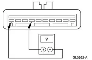
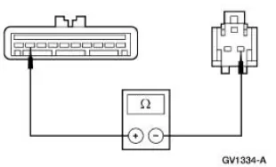
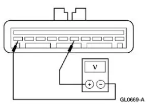
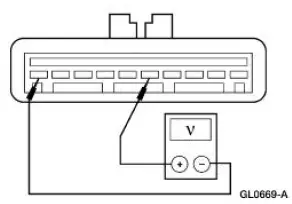
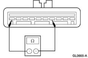
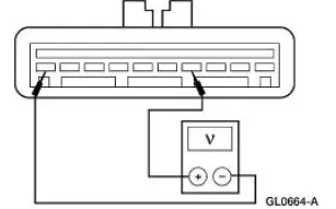
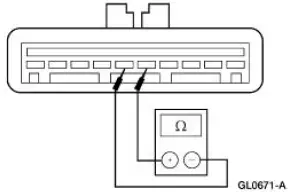
| A1 CHECK THE SPEED CONTROL SERVO VOLTAGE AND GROUND | Yes GO to A3 . No GO to A2 . |
|
|
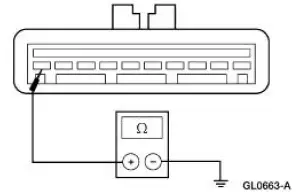
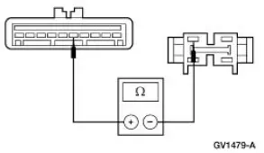
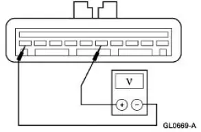
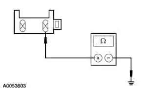
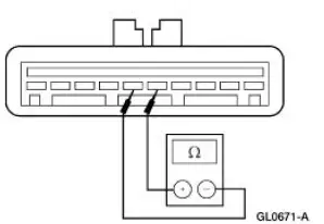
| A2 CHECK THE CIRCUIT 1205 (BK) FOR AN OPEN | Yes REPAIR Circuit 294 (WH/LB). TEST the system for normal operation. No REPAIR Circuit 1205 (BK). TEST the system for normal operation. |
|
|
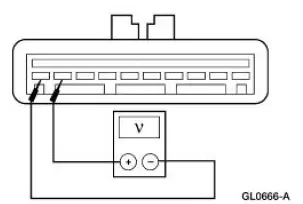
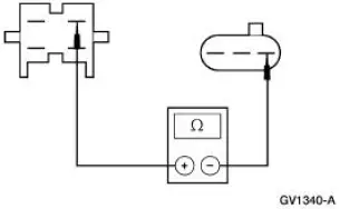
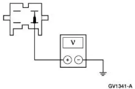
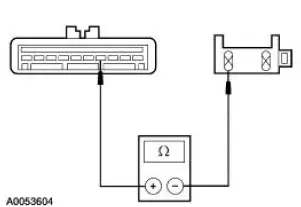
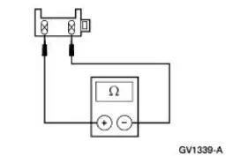
| A3 CHECK DEACTIVATOR SWITCH CIRCUITRY | Yes GO to A6 . No GO to A4 . |
|
|
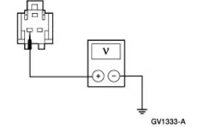
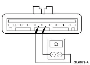
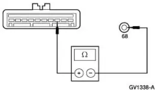
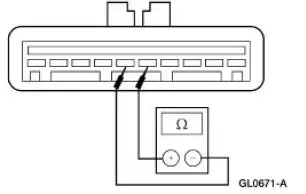
| A4 CHECK CIRCUIT 10 (LG/RD) FOR AN OPEN | Yes GO to A5 . No REPAIR the circuit. TEST the system for normal operation. |
|
|
| A5 CHECK CIRCUIT 636 (OG) FOR AN OPEN | Yes INSTALL a new deactivator switch; REFER to Switch- Deactivator . TEST the system for normal operation. No REPAIR the circuit. TEST the system for normal operation. |
|
|
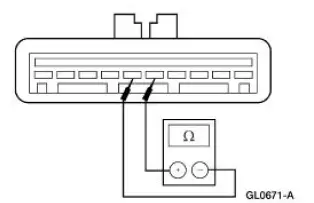
| A6 CHECK THE SPEED CONTROL ACTUATOR SWITCH ON CIRCUITRY | Yes GO to A9 . No GO to A7 . |
|
|
| A7 CHECK CIRCUIT 151 (LB/BK) FOR AN OPEN | Yes GO to A8 . No REPAIR the circuit. TEST the system for normal operation. |
|
|
| A8 CHECK THE AIR BAG SLIDING CONTACT | Yes INSTALL a new speed control actuator switch; REFER to Switch- Speed Control Actuator . TEST the system for normal operation. No INSTALL a new air bag sliding contact; REFER to Section. TEST the system for normal operation. |
|
|
| A9 CHECK THE SPEED CONTROL ACTUATOR SWITCH ON CIRCUITRY FOR SHORT TO POWER | Yes GO to A10 . No GO to A12 . |
|
|
| A10 CHECK CIRCUIT 151 (LB/BK) FOR SHORT TO POWER | Yes REPAIR the circuit. TEST the system for normal operation. No GO to A11 . |
|
|
| A11 CHECK THE AIR BAG SLIDING CONTACT | Yes INSTALL a new air bag sliding contact; REFER to Section. TEST the system for normal operation. No INSTALL a new speed control actuator switch; REFER to Switch- Speed Control Actuator . TEST the system for normal operation. |
|
|
| A12 CHECK THE SPEED CONTROL ACTUATOR SET/ACCEL CIRCUITRY | Yes GO to A13 . No INSTALL a new speed control actuator switch; REFER to Switch- Speed Control Actuator . TEST the system for normal operation. |
|
|
| A13 CHECK THE BPP SWITCH CIRCUITRY | Yes GO to A16 . No If automatic transmission, REPAIR Circuit 511 (LG) and Circuit 810 (LG/RD) as necessary. TEST the system for normal operation. If manual transmission, GO to A14 . |
|
|
| A14 CHECK CIRCUIT 511 (LG) AND CIRCUIT 810 (RD/LG) FOR AN OPEN | Yes GO to A15 . No REPAIR Circuit 511 (LG) and Circuit 810 (LG/RD) as necessary. TEST the system for normal operation. |
|
|
| A15 CHECK CIRCUIT 511 (LG) FOR AN OPEN | Yes INSTALL a new CPP switch. TEST the system for normal operation. No REPAIR the circuit. TEST the system for normal operation. |
|
|
| A16 CHECK CIRCUIT 239 (WH/OG) FOR AN OPEN | Yes GO to A17 . No REPAIR the circuit. TEST the system for normal operation. |
|
|
| A17 CHECK THE SPEED CONTROL SERVO | Yes INSTALL a new speed control servo; REFER to Actuator-Speed Control Servo . TEST the system for normal operation. No INSTALL a new PCM; REFER to Section. TEST the system for normal operation. |
|
PINPOINT TEST B: THE SET SPEED FLUCTUATES
| Test Step | Result / Action to Take |
| B1 CHECK THAT CONDITION OCCURS ONLY WHILE USING SPEED CONTROL | Yes REPAIR engine as necessary. TEST the system for normal operation. No GO to B2 . |
|
|
| B2 CHECK THE SPEED CONTROL ACTUATOR CABLE | Yes GO to B3 . No INSTALL a new speed control actuator cable; REFER to Actuator Cable-Speed Control . TEST the system for normal operation. |
|
|
| B3 CHECK THE SPEED CONTROL SERVO | Yes INSTALL a new speed control servo; REFER to Actuator-Speed Control Servo . TEST the system for normal operation. No INSTALL a new PCM; REFER to Section. TEST the system for normal operation. |
|
PINPOINT TEST C: THE SPEED CONTROL DOES NOT DISENGAGE WHEN THE BRAKES ARE APPLIED
| Test Step | Result / Action to Take |
| C1 CHECK THE BPP SWITCH CIRCUITRY | Yes INSTALL a new speed control servo; REFER to Actuator-Speed Control Servo . TEST the system for normal operation. No REPAIR Circuit 810 (RD/LG) and Circuit 511 (LG) as necessary. TEST the system for normal operation. |
|
PINPOINT TEST D: THE SPEED CONTROL DOES NOT DISENGAGE WHEN THE CLUTCH IS APPLIED
| Test Step | Result / Action to Take |
| D1 CHECK THE CLUTCH PEDAL POSITION (CPP) SWITCH | Yes INSTALL a new speed control servo; REFER to Actuator-Speed Control Servo . TEST the system for normal operation. No INSTALL a new CPP switch. TEST the system for normal operation. |
|
PINPOINT TEST E: THE SPEED CONTROL SWITCH IS INOPERATIVE-COAST
| Test Step | Result / Action to Take |
| E1 CHECK THE SPEED CONTROL ACTUATOR SWITCH | Yes INSTALL a new speed control servo; REFER to Actuator-Speed Control Servo . TEST the system for normal operation. No INSTALL a new speed control actuator switch; REFER to Switch- Speed Control Actuator . TEST the system for normal operation. |
|
PINPOINT TEST F: THE SPEED CONTROL SWITCH IS INOPERATIVE-SET/ACCEL
| Test Step | Result / Action to Take |
| F1 CHECK THE SPEED CONTROL ACTUATOR SWITCH | Yes INSTALL a new speed control servo; REFER to Actuator-Speed Control Servo . TEST the system for normal operation. No INSTALL a new speed control actuator switch; REFER to Switch- Speed Control Actuator . TEST the system for normal operation. |
|
PINPOINT TEST G: THE SPEED CONTROL SWITCH IS INOPERATIVE - RESUME
| Test Step | Result / Action to Take |
| G1 CHECK THE SPEED CONTROL ACTUATOR SWITCH | Yes INSTALL a new speed control servo; REFER to Actuator-Speed Control Servo . TEST the system for normal operation. No INSTALL a new speed control actuator switch; REFER to Switch- Speed Control Actuator . TEST the system for normal operation. |
|
PINPOINT TEST H: THE SPEED CONTROL SWITCH IS INOPERATIVE-OFF
| Test Step | Result / Action to Take |
| H1 CHECK THE SPEED CONTROL ACTUATOR SWITCH | Yes INSTALL a new speed control servo; REFER to Actuator-Speed Control Servo . TEST the system for normal operation. No INSTALL a new speed control actuator switch; REFER to Switch- Speed Control Actuator . TEST the system for normal operation. |
|
Switch Adjustment -Deactivator
1. Adjust the deactivator switch.
1. Disconnect the switch hook from the brake pedal.
2. Depress the switch hook and plunger into the deactivator switch body until the adjustment locking tab snaps into place within the hook.
3. Depress the brake pedal and reattach the switch hook.
 Symptom Chart
NOTE: New speed control diagnostic software is available in Version 12
or higher for the diagnostic
tool. When using this software, it is necessary to use Next Generation Speed
Control Adapter 007-
...
 Actuator Cable - Speed Control
1. Remove the speed control actuator cable end from the throttle body.
1. Lift the speed control cable from the throttle nailhead.
2. Release the speed control cable from the throttle bracket.
...
Other materials:
Safety Belt Tongue Rotated on Belt
1. Grasp the belt tongue and pull the belt webbing down to form a loop
through the upper (longer
and narrower) slot in the tongue.
2. Rotate and fold the belt webbing over itself within the slot to remove the
twist.
3. Pull the excess belt webbing back th ...
Component Test
Windshield Wiper Motor
CAUTION: Do not handle the wiper motor abusively when
diagnosing the wiper
operations. Failure to follow this caution may result in damage to the
motor magnets and will
make the wiper motor inoperative. Rough handling of new ...
Caliper (DISASSEMBLY AND ASSEMBLY)
Disassembly
1. Remove the disc brake caliper (2B120). For additional information,
refer to Caliper in this
section.
2. Drain the remaining brake fluid from disc brake caliper.
3. Apply low air pressure to the fluid port in the disc brake caliper.
...
