Ford Mustang (1999-2004) Service Manual: Pinpoint Tests
PINPOINT TEST A: THE CONTROL ILLUMINATION IS INOPERATIVE
| Test Step | Result / Action to Take |
| A1 CHECK PARKING LAMPS | Yes Place the headlamp switch in the OFF position. GO to A2 . No REFER to Section. |
|
|
| A2 CHECK HEADLAMP SWITCH | Yes RECONNECT the headlamp switch. GO to A3 . No INSTALL a new headlamp switch. REFER to Section. TEST the system for normal operation. |
|
|
| A3 CHECK CIRCUIT 1045 (DB/WH) | Yes REPAIR circuit 19 (LB/RD). TEST the system for normal operation. No REPAIR circuit 1045 (DB/WH). TEST the system for normal operation. |
|
PINPOINT TEST B: THE INSTRUMENT CLUSTER ILLUMINATION IS INOPERATIVE
| Test Step | Result / Action to Take |
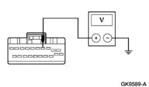
| B1 CHECK VOLTAGE TO INSTRUMENT CLUSTER ILLUMINATION | Yes GO to B2 . No REPAIR the circuit. TEST the system for normal operation. |
|
|
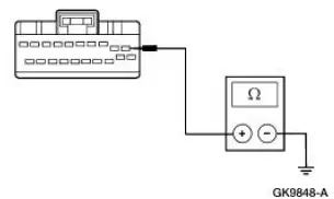
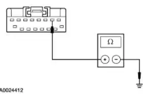
| B2 CHECK GROUND TO INSTRUMENT CLUSTER | Yes INSTALL a new instrument cluster. REFER to Section. TEST the system for normal operation. No REPAIR the circuit. TEST the system for normal operation. |
|
PINPOINT TEST C: THE CLIMATE CONTROL ILLUMINATION IS INOPERATIVE
| Test Step | Result / Action to Take |
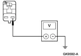
| C1 CHECK VOLTAGE TO CLIMATE CONTROL ILLUMINATION | Yes GO to C2 . No REPAIR the circuit. TEST the system for normal operation. |
|
|
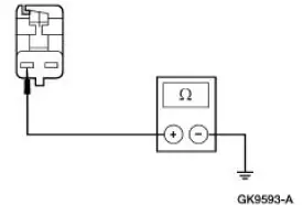
| C2 CHECK GROUND TO CLIMATE CONTROL | Yes INSTALL new illumination bulb(s). REFER to Section . No REPAIR the circuit. TEST the system for normal operation. |
|
PINPOINT TEST D: THE AUDIO SYSTEM ILLUMINATION IS INOPERATIVE
| Test Step | Result / Action to Take |
| D1 CHECK VOLTAGE TO AUDIO UNIT | Yes GO to D2 . No REPAIR the circuit. TEST the system for normal operation. |
|
|
| D2 CHECK GROUND TO AUDIO UNIT | Yes REMOVE the audio unit and SEND it to an authorized Ford audio systems repair facility. TEST the system for normal operation. No REPAIR the circuit. TEST the system for normal operation. |
|

PINPOINT TEST E: A SINGLE ILLUMINATION SOURCE IS INOPERATIVE
| Test Step | Result / Action to Take |
| E1 CHECK VOLTAGE TO THE SINGLE ILLUMINATION SOURCE | Yes GO to E2 . No REPAIR the circuit. TEST the system for normal operation. |
|
|
| E2 CHECK SINGLE ILLUMINATION SOURCE GROUND | Yes INSTALL a new component in question. TEST the system for normal operation. No REPAIR the circuit. TEST the system for normal operation. |
|
Instrument Cluster Bulb
Removal and Installation
1. Remove the instrument cluster. For additional information, refer to Section.
2. Remove the necessary instrument cluster bulbs by rotating the bulb one quarter turn counterclockwise and lifting straight out of the instrument cluster.
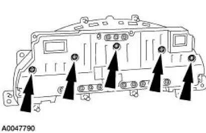
3. To install, reverse the removal procedure.
 Inspection and Verification
NOTE: A new instrument cluster must be reconfigured.
NOTE: The instrument panel dimmer switch is a part of the headlamp
switch.
1. Verify the customer concern.
2. Visually inspect for obvious signs ...
 Instrument Cluster (Description and Operation)
The instrument cluster (10849) consists of the following components:
Instrument Cluster-Base 3.8L Engine
Instrument Cluster-Base 4.6L Engine
Instrument Cluster-Cobra
...
Other materials:
Flexplate
Removal and Installation
1. Remove the transmission. For additional information, refer to Section.
2. Remove the six bolts retaining the flexplate to crankshaft, and remove the
flexplate.
3. To install, reverse the removal procedure.
Tighten the bolts in ...
Bypass Tube - 3.8L
Material
Item
Specification
Motorcraft Premium Gold
Engine Coolant
VC-7-A (in Oregon VC-7-B)
(yellow color)
WSS-M97B51-
A1
Removal and Installation
1. Drain the engine coolant. For additional information, refer to Cooling
System Dra ...
Brake Shift Interlock Actuator
Removal
1. Remove the shifter top control panel.
2. Disconnect the electrical connectors.
3. Remove the shifter bezel.
4. Remove the bulb from the bezel.
5. Disconnect the electrical connector.
6. CAUTION: Extra force may be needed to lift up on th ...
