Ford Mustang (1999-2004) Service Manual: Installation
1. Inspect the pinion flange seal journal for rust, nicks, and scratches prior to installing the flange.
Polish the seal journal with fine crocus cloth, if necessary.
2. Lubricate the pinion flange splines.
- Use SAE 80W-90 Premium Rear Axle Lubricant XY-80W90-QL or equivalent meeting Ford specification WSP-M2C197-A.
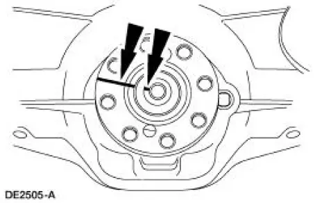
3. NOTE: Disregard the index marks if installing a new pinion flange.
Position the pinion flange.
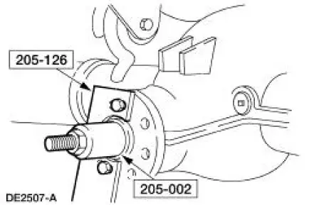
4. Using the special tools, install the pinion flange.
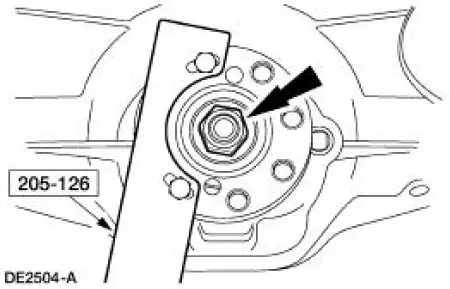
5. CAUTION: Do not under any circumstance loosen the nut to reduce preload. If it is necessary to reduce preload, install a new collapsible spacer (4662) and nut.
CAUTION: Remove the special tool while taking preload readings with the Nm (inch/pound) torque wrench.
Tighten the nut to set the preload.
- Rotate the drive pinion occasionally to make sure the differential pinion bearings (4630) (4621) seat correctly. Take frequent differential pinion bearing torque preload readings by rotating the drive pinion with a Nm (inch/pound) torque wrench.
- If the preload recorded prior to disassembly is lower than the specification for used bearings, then tighten the nut to specification. If the preload recorded prior to disassembly is higher than the specification for used bearings, then tighten the nut to the original reading as recorded.
- Refer to the torque specification for used differential pinion bearings in the Specifications portion of this section.
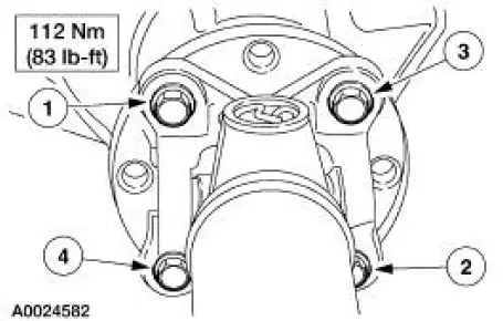
6. CAUTION: Align the index marks.
CAUTION: Install the driveshaft with new bolts. If new bolts are not available, apply Threadlock and Sealer EOAZ-19554-AA or equivalent meeting Ford specification WSKM2G351- A5 to the threads of the original bolts.
CAUTION: The driveshaft centering socket yoke fits tightly on the pinion flange pilot. To make sure that the yoke seats squarely on the flange, tighten the bolts evenly in a cross pattern as shown.
Connect the driveshaft.
7. Install the rear brake calipers.
8. Install the rear wheel and tire assemblies.
9. Lower the vehicle.
 Removal
1. Raise and support the vehicle.
2. Remove the rear wheel and tire assemblies.
3. CAUTION: Remove the rear brake calipers to prevent drag during the
drive pinion
bearing preload adjustment.
CAU ...
 Differential Housing Cover
Removal
1. Raise and support the vehicle.
2. NOTE: Empty the lubricant into a clean container for reuse.
Remove the differential housing cover (4033).
1. Remove the 10 bolts and drain the lubrica ...
Other materials:
Fluid Pan, Gasket and Filter
Material
Item
Specification
MERCON V Automatic
Transmission Fluid
XT-5-QM, XT-5-DM
MERCON V
1. Normal maintenance requires periodic automatic transmission fluid changes.
If a major repair,
such as a clutch, band, bearing, etc., is requir ...
Intake Air Distribution and Filtering - Supercharger,
Charge Air Cooler
The supercharger (SC) is a positive displacement pump. Its purpose is to
supply an excess volume of
intake air to the engine by increasing air pressure and density in the
intake manifold. The supercharger
is matched to the engine by its displacement and ...
Brake Disc Machining
Special Tool(s)
Gauge, Clutch Housing
308-021 (T75L-4201-A)
Dial Indicator Gauge with
Holding Fixture
100-002 (TOOL-4201-C) or
equivalent
Material
Item
Specification
Metal Surface Cleaner
F4AZ-19A536-RA or equiv ...
