Ford Mustang (1999-2004) Service Manual: Rear Drive Axle and Differential
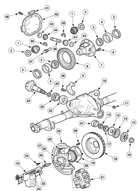
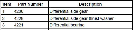
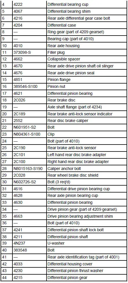
- The axle housing assembly consists of a cast center section with two steel tube assemblies and a stamped differential housing cover (4033). The differential housing cover uses silicone sealant as a gasket.
- The hypoid-design gearset consists of 8.8-inch ring gear (4209) and a
drive pinion gear (4209).
Two opposed tapered roller bearings support the drive pinion in the axle housing (4010).
- A collapsible spacer (4662), located on the differential pinion shaft, maintains pinion bearing preload. The pinion nut (389546-S100) adjusts the preload.
- Differential bearing shims (4067), located between the differential bearing cups (4222) and the rear axle housing, adjust the differential bearing preload and the ring gear backlash.
- The differential case (4204) is a one-piece design with two openings to allow for assembly of the internal components and lubricant flow. Two opposed tapered roller bearings (differential bearings) (4221) support the differential case in the axle housing. Removable bearing caps (4010) retain the differential assembly in the axle housing.
- Inside the differential case, the differential pinion shaft (4211) supports two differential pinion gears (4215). The pinion gears engage the differential side gears (4236), to which the axle shafts (4234) are splined. The differential pinion shaft lock bolt (4241) retains the differential pinion shaft in the differential case.
- An embossed metal tag, bolted to the differential housing cover, contains rear axle identification.
 Rear Drive Axle/Differential - Ford 8.8-Inch Ring Gear
General Specifications
Torque Specifications
Description
Nm
lb-ft
lb-in
Bolt retaining the differential pinion shaft to the
differential case
30
22
-
Bolt retaining t ...
Other materials:
Moulding - Roof Side
Removal and Installation
1. Remove the weatherstrip.
2. Remove the exterior roof side moulding screws.
3. Remove the interior roof side moulding screws.
4. Remove the roof side moulding screw.
5. Release the clips.
1. Lift up to release the two ...
Transmission Connector Layouts
Transmission Vehicle Harness Connector
Transmission Internal Harness Connector
Digital Transmission Range (TR) Sensor Connector
Output Shaft Speed (OSS) Sensor Harness Connector
Digital Transmission Range (TR) Senso ...
Symptom Chart
Condition
Possible Sources
Action
Dogtracking
Excessive rear
thrust angle.
Front or rear
suspension
components.
Drive axle
damaged.
CHECK the wheel alignment.
ADJUST as necessary
INSPE ...
