Ford Mustang (1999-2004) Service Manual: Piston - Pin Diameter
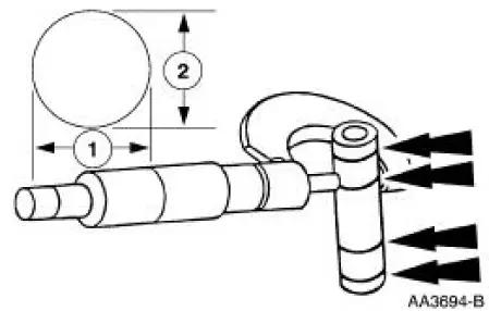
1. Measure the piston pin diameter in two directions at the points shown. Verify the diameter is within specification.
- Refer to the appropriate section in Group for the procedure.
- If out of specification, install new components as necessary. Refer to the appropriate section in Group for the procedure.
Connecting Rod -Cleaning
CAUTION: Do not use a caustic cleaning solution or damage to connecting rods can occur.
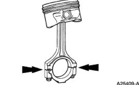
1. NOTE: The connecting rod large end is a matched set. The connecting rod cap must be installed on the original connecting rod in the original position. Do not reverse the cap. Parts are not interchangeable.
Mark and separate the parts and clean with solvent. Clean the oil passages.
Connecting Rod -Large End Bore
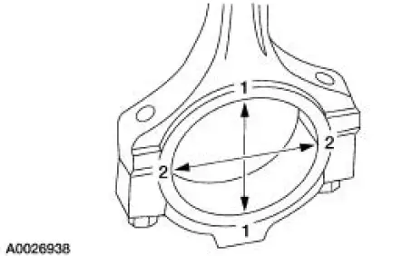
1. Tighten the bolts to specification, then measure the bore in two directions. The difference is the connecting rod bore out-of-round. Verify the out-of-round is within specification.
- Refer to the appropriate section in Group for the procedure.
- If out of specification, install new components as necessary. Refer to the appropriate section in Group for the procedure.
 Piston - Ring-to-Groove Clearance
1. Inspect the piston for ring land damage or accelerated wear.
2. Measure the piston ring-to-groove clearance.
Refer to the appropriate section in Group for the procedure.
If out of specifica ...
 Connecting Rod - Bushing Diameter
1. Measure the inner diameter of the connecting rod bushing, if equipped.
Verify the diameter is
within specification.
Refer to the appropriate section in Group for the procedure.
If out of s ...
Other materials:
Antenna (Removal and Installation)
Removal
1. Lower the glove compartment by releasing the stops from the
instrument panel.
2. Disconnect the antenna in-line connector
3. Remove the antenna base and cable.
1. Remove the radio antenna base cap.
2. Remove the screws.
3. Re ...
Cylinder Head
Special Tool(s)
Compressor, Valve Spring
303-163 (T81P-6513-A)
Material
Item
Specification
SAE 5W-20 Premium Synthetic
Blend Motor Oil
XO-5W20-QSP or equivalent
WSS-M2C153-
H
Disassembly and Assembly
CAUTION: If the com ...
Cabin air filter
Note: Make sure you have a cabin air filter installed at all times.
This
prevents foreign objects from entering the system. Running the system
without a filter in place could result in degradation or damage to the
system.
Your vehicle is equipped with a cabi ...
