Ford Mustang (1999-2004) Service Manual: Radiator
Material
| Item | Specification |
| Motorcraft Premium Gold Engine Coolant VC-7-A (in Oregon VC-7-B) (yellow color) | WSS-M97B51- A1 |
Removal and Installation
NOTE: Radiator removal and installation is similar for both 3.8L and 4.6L vehicles. The art shown in the procedure is the 4.6L engine.
Mach I
1. Remove the air intake scoop. For additional information, refer to Section.
All vehicles
2. Drain the engine cooling system. For additional information, refer to Cooling System Draining, Filling and Bleeding in this section.
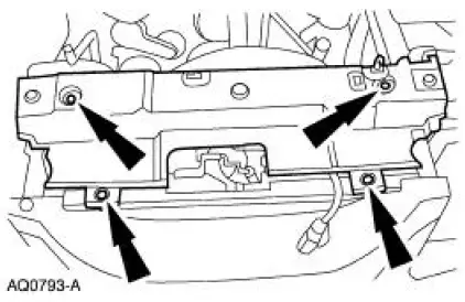
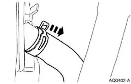
3. Remove the radiator sight shield.
- Release the clips.
4. Remove the fan blade, fan motor and fan shroud assembly. For additional information, refer to Cooling Fan Motor and Shroud in this section.
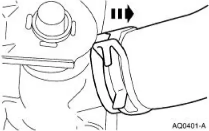
5. Remove the upper radiator hose from the radiator.
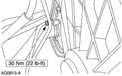
6. NOTE: To avoid disturbing the transmission oil cooler fittings, use a backup wrench.
If equipped, remove the transmission lower cooler tube fitting.
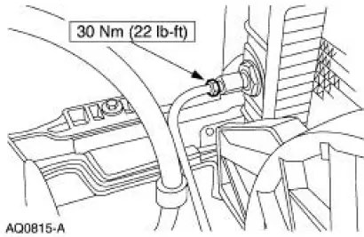
7. NOTE: To avoid disturbing the transmission oil cooler fittings, use a backup wrench.
If equipped, remove the upper transmission cooler tube fitting.
8. Remove the lower radiator hose from the radiator.
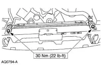
9. Remove the radiator supports.
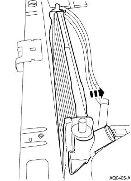
10. Remove the radiator.
11. To install, reverse the removal procedure.
12. Fill and bleed the cooling system. For additional information, refer to Cooling System Draining, Filling and Bleeding in this section.
Mach I
13. Install the air intake scoop. For additional information, refer to Section.
 Water Pump - 4.6L(2V) and 4.6L(4V)
Material
Item
Specification
Motorcraft Premium Gold
Engine Coolant
VC-7-A (in Oregon VC-7-B)
(yellow color)
WSS-M97B51-
A1
Removal and Installation
Mach I
1. Remove the air ...
 Cooling Fan Motor and Shroud
Removal and Installation
1. Disconnect the battery ground cable.
2. Remove the degas bottle or coolant expansion tank. For additional
information, refer to Degas
Bottle-4.6L(2V) and 4.6L(4V) in this ...
Other materials:
Assembly
1. NOTE: Universal joint service kits are to be installed as complete
assemblies only. Do not mix
components from other U-joint kits.
Install the bearing cup.
1. Start a new bearing cup into the driveshaft yoke.
Check the needle bearings for correct po ...
Lumbar Motor
Removal and Installation
All vehicles
1. Remove the front seat. For additional information, refer to Seat-Front
Power in this section.
2. Disconnect the power seat track electrical connector.
3. Remove the four seat track bolts.
Vehicles with standar ...
Output Shaft
Special Tool(s)
Remover, Drive Pinion Bearing
Cone
205-D002 (D79L-4621-A) or
equivalent
Installer, Drive Pinion Bearing
Cone
205-011 (T57L-4621-B)
...
