Ford Mustang (1999-2004) Service Manual: Water Pump - 4.6L(2V) and 4.6L(4V)
Material
| Item | Specification |
| Motorcraft Premium Gold Engine Coolant VC-7-A (in Oregon VC-7-B) (yellow color) | WSS-M97B51- A1 |
Removal and Installation
Mach I
1. Remove the air intake scoop. For additional information, refer to Section.
Cobra
2. Remove the supercharger drive belt cover.
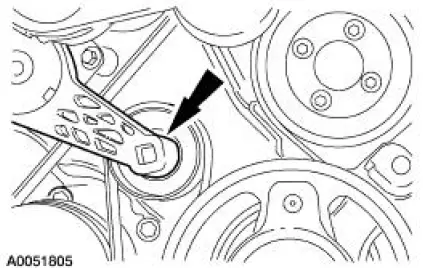
3. Rotate the supercharger belt tensioner clockwise and remove the supercharger drive belt.
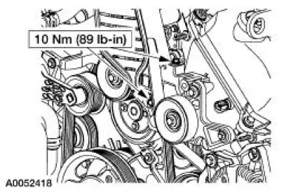
4. Remove the coolant hose mounting bolt.
5. Remove the belt idler bracket support assembly.
All vehicles
6. Drain the engine coolant. For additional information, refer to Cooling System Draining, Filling and Bleeding in this section.
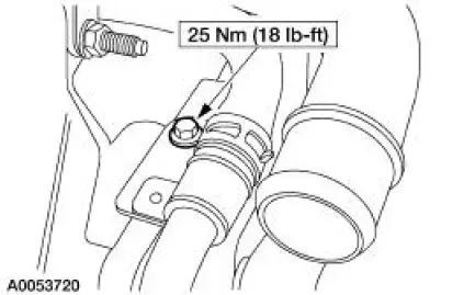
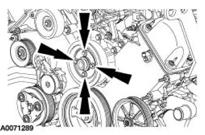
7. Loosen the coolant pump pulley bolts.
8. Remove the accessory drive belt. For additional information, refer to Section.
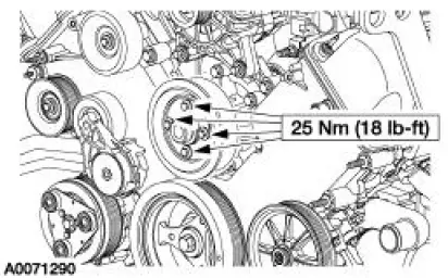
9. Remove the bolts and the coolant pump pulley.
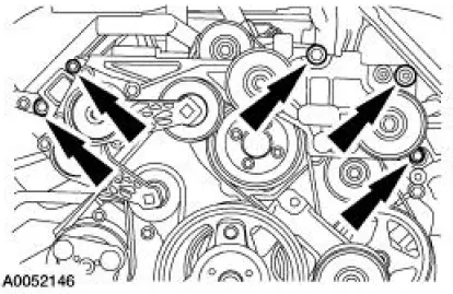
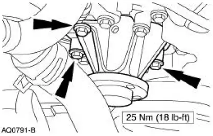
10. Remove the four bolts and the coolant pump.
11. If necessary, wipe the coolant pump mounting surface with a soft cloth.
12. CAUTION: Do not rotate the coolant pump housing once installed in the engine.
Damage to the O-ring seal can occur, causing the coolant pump to leak.
NOTE: Install a new O-ring seal and lubricate with the same clean engine coolant that is present in the system. Do not mix coolant types.
To install, reverse the removal procedure.
 Water Pump - 3.8L
Material
Item
Specification
Motorcraft Premium Gold
Engine Coolant
VC-7-A (in Oregon VC-7-B)
(yellow color)
WSS-M97B51-
A1
Removal and Installation
1. Drain the engine coola ...
 Radiator
Material
Item
Specification
Motorcraft Premium Gold
Engine Coolant
VC-7-A (in Oregon VC-7-B)
(yellow color)
WSS-M97B51-
A1
Removal and Installation
NOTE: Radiator removal an ...
Other materials:
Roadside assistance
Vehicles Sold in the U.S.: Getting Roadside Assistance
To fully assist you should you have a vehicle concern, Ford Motor
Company offers a complimentary roadside assistance program.
This program is separate from the New Vehicle Limited Warranty.
The service i ...
Stay Pad - Convertible Top
Removal
1. Remove the convertible top material. For additional information, refer to
Convertible Top
Material in this section.
2. Remove the rear window glass. For additional information, refer to
Convertible Top Assembly-
Rear Window Glass in this section. ...
Cylinder Head
Special Tool(s)
Compressor, Valve Spring
303-163 (T81P-6513-A)
Material
Item
Specification
SAE 5W-20 Premium Synthetic
Blend Motor Oil
XO-5W20-QSP or equivalent
WSS-M2C153-
H
Disassembly and Assembly
CAUTION: If the com ...
