Ford Mustang (1999-2004) Service Manual: Refrigerant System Tests
Special Tool(s)
 |
R-134a Manifold Gauge Set 176-R032A or equivalent |
1. Connect the R-134a Manifold Gauge Set. For additional information, refer to Manifold Gauge Set Connection in this section.
2. Adjust the climate controls for maximum cooling.
- Start the engine.
- Select MAX A/C operation.
- Set the blower motor speed to maximum.
3. Stabilize the in-vehicle temperature at 21-27C (70-80F).
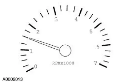
4. NOTE: When the ambient temperatures exceed 38C (100F), do not run the engine above normal idle speed.
Maintain the engine speed at 1,500 rpm.
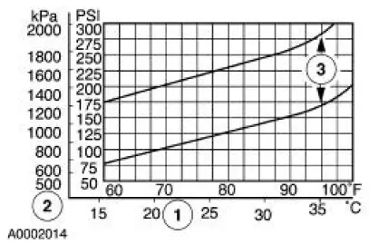
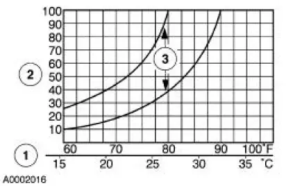
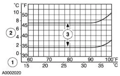
5. Determine the compressor discharge (high) pressure.
1. Record the ambient temperature.
2. Record the discharge (high) pressure.
3. NOTE: In ambient temperatures between 38-43C (100-110F), the system performance pressures will be the same as those for ambient temperatures shown on the chart in the 32-38C (90-100F) range.
The system performance is acceptable when the pressure reading falls between the upper and lower limits shown.
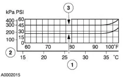
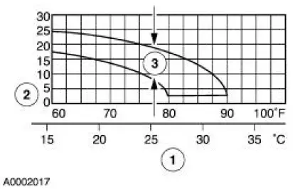
6. Determine the compressor suction (low) pressure.
1. Record the ambient temperature.
2. Record the suction (low) pressure.
3. NOTE: In ambient temperatures between 38-43C (100-110F), the system performance pressures will be the same as those for ambient temperatures shown on the chart in the 32-38C (90-100F) range.
The system performance is acceptable when the pressure reading falls between the upper and lower limits shown.
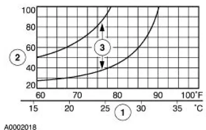
7. Determine the A/C clutch ON time.
1. Record the ambient temperature.
2. Record the A/C clutch ON time in seconds.
3. NOTE: When the ambient temperature is above 26C (80F), the A/C clutch may not cycle.
The system performance is acceptable when the recorded time falls between the upper and lower limits shown.
8. Determine the A/C clutch OFF time.
1. Record the ambient temperature.
2. Record the A/C clutch OFF time in seconds.
3. NOTE: When the ambient temperature is above 26C (80F), the A/C clutch may not cycle.
The system performance is acceptable when the recorded time falls between the upper and lower limits shown.
9. Determine the total A/C clutch cycle time.
1. Record the ambient temperature.
2. Record the time the A/C clutch is engaged plus the time it is disengaged (time ON plus time OFF).
3. NOTE: When the ambient temperature is above 26C (80F), the A/C clutch may not cycle.
The system performance is acceptable when the recorded time falls between the upper and lower limits shown.
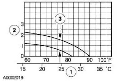
10. Determine the A/C clutch cycle rate per minute.
1. Record the ambient temperature.
2. Record the number of A/C clutch cycles occurring in one minute.
3. NOTE: When the ambient temperature is above 26C (80F), the A/C clutch may not cycle.
The system performance is acceptable when the recorded number of cycles falls between the upper and lower limits shown.
11. Determine the center A/C register discharge temperature.
1. Record the ambient temperature.
2. Record the center A/C register discharge temperature.
3. NOTE: In ambient temperatures between 38-43C (100-110F), the A/C register discharge temperatures will be the same as those for ambient temperatures shown on the chart in the 32-38C (90-100F) range.
The system performance is acceptable when the center A/C register discharge temperature falls between the upper and lower limits shown.
Air Conditioning (A/C) Clutch Air Gap Adjustment
1. Check the A/C clutch air gap at three equally-spaced places between the A/C clutch hub (2884) and the A/C clutch pulley (2E884).
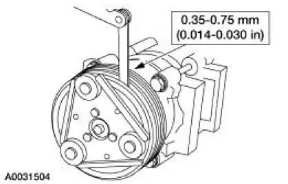
2. Remove the A/C clutch. Add or remove spacers between the A/C clutch and the compressor shaft until clearance is within specification. For additional information, refer to Section.
 Air Conditioning Line (Peanut) Fitting
Disconnect
1. CAUTION: Support the female fitting with a wrench to prevent the
tubes from
twisting.
Remove the nut from the peanut fitting.
2. Pull the peanut fitting apart.
3. CAUTION: Do not us ...
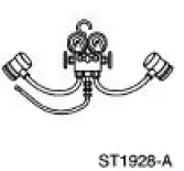
 Manifold Gauge Set Connection
Special Tool(s)
R-134a Manifold Gauge Set
176-R032A or equivalent
1. Turn both valves on the R-134a Manifold Gauge Set clockwise to close the
low- and highpressure
hoses to the center ...
Other materials:
Clutch Pedal Position (CPP) Switch
Removal
1. Disconnect the battery ground cable. For additional information,
refer to Section.
2. Disconnect the connector.
3. Remove the bolt and the clutch pedal position (CPP) switch.
Installation
1. To install, reverse the removal procedure. ...
SYNC®
SYNC is an in-vehicle communications system that works with your
Bluetooth-enabled cellular phone and portable media player. This allows
you to:
• Make and receive calls.
• Access and play music from your portable music player.
• Use 911 Assist, Vehicle ...
Exhaust System Neutralizing
WARNING: Exhaust gases contain carbon monoxide, which is harmful to
health and
potentially lethal. Repair exhaust system leaks immediately. Never operate the
engine in an
enclosed area.
WARNING: Exhaust system components are hot.
NOTE: Neutralize the exhau ...
