
Ford Mustang (1999-2004) Service Manual: Removal
1. Remove the A/C compressor (19703). For additional information, refer to Air Conditioning (A/C) Compressor-3.8L or Air Conditioning (A/C) Compressor-4.6L in this section.
2. Remove the bolt.
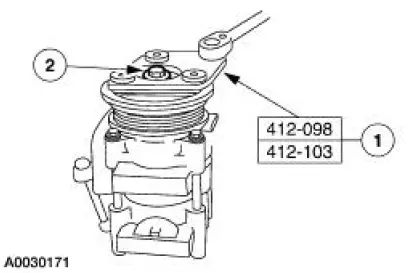
1. Hold the A/C disc and hub assembly (19D786) with the special tool.
2. Remove the bolt.
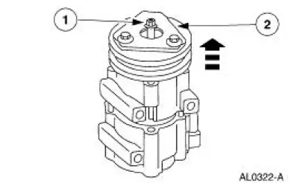
3. Remove the A/C disc and hub assembly and the A/C clutch hub spacer (19D648).
1. Thread an 8 x 1.25 mm bolt into the A/C clutch to force it from the compressor shaft.
2. Lift the A/C disc and hub assembly and the A/C clutch hub spacer from the compressor shaft.
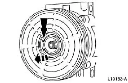
4. Remove the pulley snap ring.
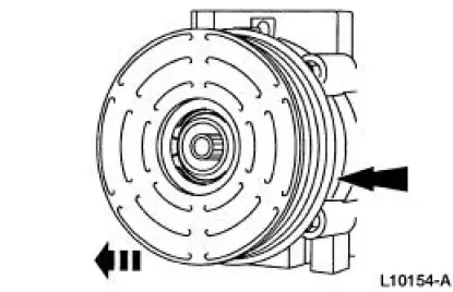
5. Remove the A/C clutch pulley (2E884).
6. CAUTION: Do not use air tools. The A/C clutch field coil (19D798) can be easily damaged.
Remove the A/C clutch field coil.
1. Note the location of the A/C clutch field coil electrical connector.
2. Install the special tool on the nose opening of the A/C compressor.
3. Install the special tool.
4. Remove the A/C clutch field coil.
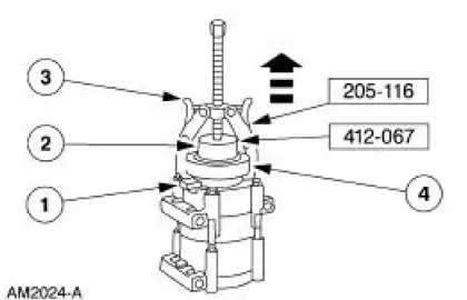
 Clutch And Clutch Field Coil
Special Tool(s)
2-Jaw Puller
205-D026 (D80L-1002-L) or
equivalent
Installer, A/C Compressor Coil
412-065 (T89P-19623-EH)
Holding Fixture, Compressor
Clutch ( ...
 Installation
1. Clean the A/C disc and field coil and pulley mounting surfaces.
2. CAUTION: Do not use air tools. The A/C clutch field coil can be easily
damaged.
Install the A/C clutch field coil.
1. Place th ...
Other materials:
Moulding - Roof Side
Removal and Installation
1. Remove the weatherstrip.
2. Remove the exterior roof side moulding screws.
3. Remove the interior roof side moulding screws.
4. Remove the roof side moulding screw.
5. Release the clips.
1. Lift up to release the two ...
Cable and Conduit
Removal
NOTE: The RH rear is shown, the LH is similar.
1. CAUTION: If any component in the parking brake system requires
repair or if the
rear axle housing (4010) is removed, the cable tension must be released.
Release the cable tension. For additional ...
Installation
1. Clean the A/C disc and field coil and pulley mounting surfaces.
2. CAUTION: Do not use air tools. The A/C clutch field coil can be easily
damaged.
Install the A/C clutch field coil.
1. Place the A/C clutch field coil on the A/C compressor with the A/C
...
