
Ford Mustang (1999-2004) Service Manual: Installation
1. Clean the A/C disc and field coil and pulley mounting surfaces.
2. CAUTION: Do not use air tools. The A/C clutch field coil can be easily damaged.
Install the A/C clutch field coil.
1. Place the A/C clutch field coil on the A/C compressor with the A/C clutch field coil electrical connector correctly positioned.
2. Using the special tools, install the A/C field coil.
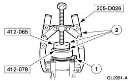
3. NOTE: The A/C clutch pulley is a tight fit on the A/C compressor head. It must be correctly aligned during installation.
Install the A/C clutch pulley.
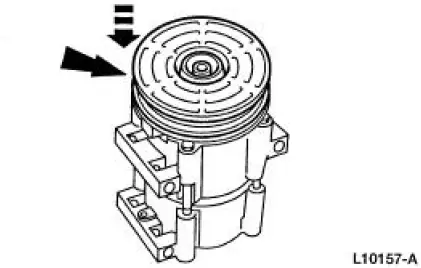
4. Install the pulley snap ring with the bevel side out.
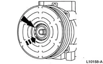
5. Place one nominal thickness A/C clutch hub spacer inside the clutch hub spline opening.
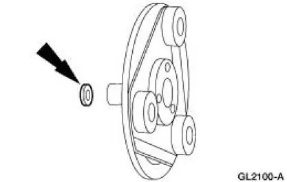
6. Install the A/C clutch.
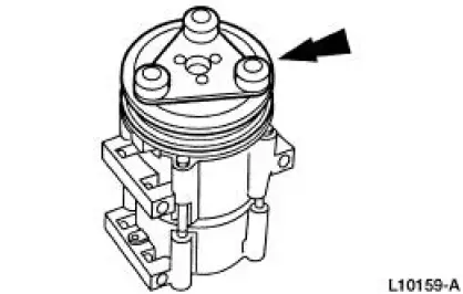
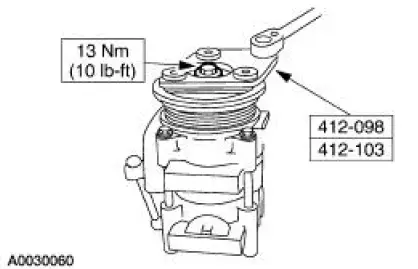
7. Using the special tool, install the A/C disc and hub assembly retaining bolt.
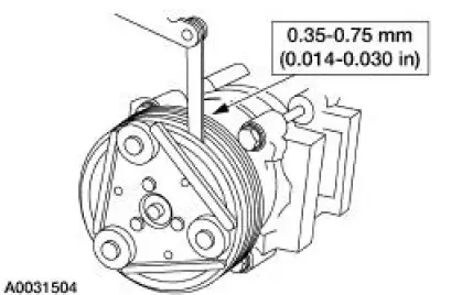
8. Measure and adjust the clutch air gap by removing or adding A/C clutch hub spacers.
9. Install the A/C compressor. For additional information, refer to Air Conditioning (A/C) Compressor-3.8L or Air Conditioning (A/C) Compressor-4.6L in this section.
 Removal
1. Remove the A/C compressor (19703). For additional information, refer to
Air Conditioning (A/C)
Compressor-3.8L or Air Conditioning (A/C) Compressor-4.6L in this section.
2. Remove the bolt.
1. ...
 Air Conditioning (A/C) Compressor Shaft Seal
Special Tool(s)
Holding Fixture, Compressor
Clutch (3.8L vehicles)
412-098 (T94P-19703-AH)
Holding Fixture, Compressor
Clutch (4.6L vehicles)
412-103 (T95L-19703-AH)
...
Other materials:
Installation
1. Lubricate the lip of the wheel bearing oil seal
Use Premium Long-Life Grease XG-1-C or equivalent meeting Ford
specification ESAM1C75-
B.
2. CAUTION: Do not damage the wheel bearing oil seal.
Install the two axle shafts.
3. CAUTION: Do not damage th ...
System Air Flow Description
MAX A/C
When MAX A/C is selected:
The air inlet door vacuum control motor is at full vacuum, closing
off outside air and admitting
only recirculated air.
The panel/defrost door vacuum control motor is at full vacuum and
the panel/floor door vacu ...
Torque Converter Leak Check
Special Tool(s)
Leak Tester, Torque Converter
307-421
1. Clean the outside surface of the torque converter.
2. Install the special tool into the converter hub.
3. WARNING: Always follow correct safety procedures while using press.
Failure t ...
