Ford Mustang (1999-2004) Service Manual: Removal
WARNING: Always wear safety glasses when repairing an air bag supplemental restraint system (SRS) vehicle and when handling an air bag module. This will reduce the risk of injury in the event of an accidental deployment.
WARNING: Carry a live air bag module with the air bag and deployment door pointed away from your body. This will reduce the risk of injury in the event of an accidental deployment.
WARNING: Do not set a live air bag module down with the deployment door face down.
This will reduce the risk of injury in the event of an accidental deployment.
WARNING: After deployment, the air bag surface can contain deposits of sodium hydroxide, a product of the gas generant combustion that is irritating to the skin. Wash your hands with soap and water afterwards.
WARNING: Never probe the connectors on the air bag module. Doing so can result in air bag deployment, which can result in personal injury.
WARNING: Air bag modules with discolored or damaged trim covers must be replaced, not repainted.
WARNING: The restraint system diagnostic tool is for restraint system service only.
Remove from vehicle prior to road use. Failure to remove could result in injury and possible violation of vehicle safety standards.
NOTE: Repair is made by installing a new part only. If the new part does not correct the condition, install the original part and perform the diagnostic procedure again.
1. Prepare the vehicle for passenger air bag module removal.
1. WARNING: To avoid accidental deployment and possible personal injury, the backup power supply must be depleted before repairing or replacing any front or side air bag supplemental restraint system (SRS) components and before servicing, replacing, adjusting or striking components near the front or side air bag sensors, such as doors, instrument panel, console, door latches, strikers, seats and hood latches.
Please refer to the appropriate vehicle shop manual to determine location of the front air bag sensors.
The side air bag sensors are located at or near the base of the B-pillar.
To deplete the backup power supply energy, disconnect the battery ground cable and wait at least one minute. Be sure to disconnect auxiliary batteries and power supplies (if equipped).
Disconnect the battery ground cable (14301) and wait at least one minute. For additional information, refer to Section.
2. WARNING: To reduce the risk of serious personal injury, read and follow all warnings, notes, and instructions in the supplemental restraint system (SRS) deactivation/reactivation procedure.
Deactivate the supplemental restraint system (SRS). For additional information, refer to Supplemental Restraint System (SRS) Deactivation and Reactivation in the General Procedures portion of this section.
2. CAUTION: Do not handle the passenger air bag module by grabbing the edges of the deployment doors.
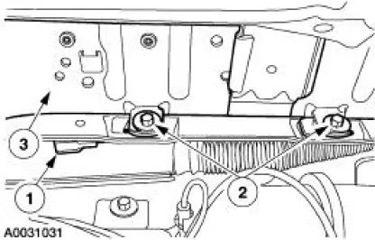
Remove the passenger air bag module.
1. Remove the passenger air bag module electrical connector from the instrument panel bracket.
2. Remove the passenger air bag module bolts.
3. Placing one hand in the glove compartment opening, push the passenger air bag module out and remove it.
 Passenger Air Bag Module
Special Tool(s)
Diagnostic Tool, Restraint
System (2 Req'd)
418-F088 (105-R0012)
...
 Installation
WARNING: To reduce the risk of serious personal injury, read
and follow all warnings,
cautions and notes at the beginning of the removal procedure.
1. Install the passenger air bag module.
...
Other materials:
Pulley - CII Pump
Special Tool(s)
Pump Pulley Installer
211-009 (T65P-3A733-C)
Pump Pulley Remover
211-016 (T69L-10300-B)
Removal
1. Remove the drive belt.
2. Using the special tool, remove the pulley.
Installation
1. Using the special tool, instal ...
Climate Control System (Diagnosis and Testing)
Refer to Wiring Diagrams Cell 54 , Air Conditioner/Heater for schematic
and connector information.
Special Tool(s)
Connector, Refrigerant
Pressure Line
412-093 (T94P-19623-E)
Set, A/C Fittings
412-DS028 (014-00333, D93L-
19703 ...
Condenser Core
Material
Item
Specification
PAG Refrigerant Compressor
Oil (R-134a Systems)
F7AZ-19589-DA (Motorcraft YN-
12-C)
WSH-M1C231-
B
Removal and Installation
NOTE: If an A/C condenser core leak is suspected, the A/C condenser
core must be l ...
