Ford Mustang (1999-2004) Service Manual: Installation
WARNING: To reduce the risk of serious personal injury, read and follow all warnings, cautions and notes at the beginning of the removal procedure.
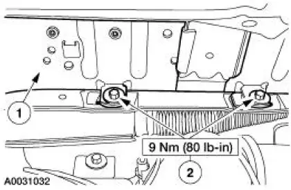
1. Install the passenger air bag module.
1. Position the passenger air bag module into the instrument panel.
2. Install the bolts.
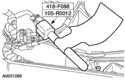
2. Remove the restraint system diagnostic tool from the vehicle harness side of the passenger air bag electrical connector.
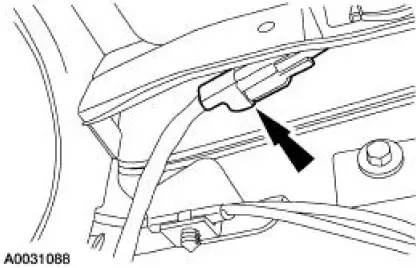
3. Connect the passenger air bag module electrical connector. Install the passenger air bag module electrical connector and pin-type retainer to the instrument panel frame.
4. Close the glove compartment.
5. Connect the battery ground cable. For additional information, refer to Section.
6. With the restraint system diagnostic tools still installed at the remaining deployable devices, prove out the supplemental restraint system (SRS). For additional information, refer to Air Bag Supplemental Restraint System (SRS) in the Diagnosis and Testing portion of this section.
7. WARNING: To avoid accidental deployment and possible personal injury, the backup power supply must be depleted before repairing or replacing any front or side air bag supplemental restraint system (SRS) components and before servicing, replacing, adjusting or striking components near the front or side air bag sensors, such as doors, instrument panel, console, door latches, strikers, seats and hood latches.
Please refer to the appropriate vehicle shop manual to determine location of the front air bag sensors.
The side air bag sensors are located at or near the base of the B-pillar.
To deplete the backup power supply energy, disconnect the battery ground cable and wait at least one minute. Be sure to disconnect auxiliary batteries and power supplies (if equipped).
Disconnect the battery ground cable and wait at least one minute. For additional information, refer to Section.
8. Restore the vehicle to operating condition.
1. WARNING: To reduce the risk of serious personal injury, read and follow all warnings, notes, and instructions in the supplemental restraint system (SRS) deactivation/reactivation procedure.
Reactivate the supplemental restraint system (SRS). For additional information, refer to Supplemental Restraint System (SRS) Deactivation and Reactivation in the General Procedures portion of this section.
2. WARNING: The restraint system diagnostic tool is for restraint system service only. Remove from the vehicle prior to road use. Failure to remove could result in injury and possible violation of vehicle safety standards.
With all the restraint system diagnostic tools removed, prove out the supplemental restraint system (SRS). For additional information, refer to Air Bag Supplemental Restraint System (SRS) in the Diagnosis and Testing portion of this section.
 Removal
WARNING: Always wear safety glasses when repairing an air bag
supplemental restraint
system (SRS) vehicle and when handling an air bag module. This will
reduce the risk of injury
in the even ...
 Clockspring
Special Tool(s)
Diagnostic Tool, Restraint
System (2 Req'd)
418-F088 (105-R0012)
...
Other materials:
Floor Console
Removal and Installation
All vehicles
1. Disconnect the battery ground cable. For additional information,
refer to Section .
2. Apply the parking brake.
Vehicles with automatic transmission
3. Place the selector lever in the 1 position.
Vehicle ...
Crankshaft Runout
Special Tool(s)
Dial Indicator Gauge with
Holding Fixture
100-002 (TOOL-4201-C) or
equivalent
1. NOTE: Crankshaft main bearing journals must be within
specifications before checking runout.
Use the Dial Indicator Gauge with Holding Fixtur ...
Wheel Hub or Axle Flange Face Runout
NOTE: If the axle shaft assembly is removed, check runout of the shaft
itself. The forged (unmachined)
part of the shaft is allowed to have as much as 3.0 mm (0.120 inch) runout. This
alone will not cause a
vibration condition.
1. Position the special tool ...
