Ford Mustang (1999-2004) Service Manual: Removal
WARNING: Always wear safety glasses when repairing an air bag supplemental restraint system (SRS) vehicle and when handling an air bag module. This will reduce the risk of injury in the event of an accidental deployment.
WARNING: Carry a live air bag module with the air bag and trim cover pointed away from your body. This will reduce the risk of injury in the event of an accidental deployment.
WARNING: Do not set a live air bag module down with the trim cover face down. This will reduce the risk of injury in the event of an accidental deployment.
WARNING: After deployment, the air bag surface can contain deposits of sodium hydroxide, a product of the gas generant combustion that is irritating to the skin. Wash your hands with soap and water afterwards.
WARNING: Never probe the connectors on the air bag module. Doing so can result in air bag deployment, which can result in personal injury.
WARNING: Air bag modules with discolored or damaged trim covers must be replaced, not repainted.
WARNING: The restraint system diagnostic tool is for restraint system service only.
Remove from vehicle prior to road use. Failure to remove could result in injury and possible violation of vehicle safety standards.
NOTE: Repair is made by installing a new part only. If the new part does not correct the condition, install the original part and perform the diagnostic procedure again.
1. Prepare the vehicle for clockspring removal.
1. WARNING: To avoid accidental deployment and possible personal injury, the backup power supply must be depleted before repairing or replacing any front or side air bag supplemental restraint system (SRS) components and before servicing, replacing, adjusting or striking components near the front or side air bag sensors, such as doors, instrument panel, console, door latches, strikers, seats and hood latches.
Please refer to the appropriate vehicle shop manual to determine location of the front air bag sensors.
The side air bag sensors are located at or near the base of the B-pillar.
To deplete the backup power supply energy, disconnect the battery ground cable and wait at least one minute. Be sure to disconnect auxiliary batteries and power supplies (if equipped).
Disconnect the battery ground cable (14301) and wait at least one minute. For additional information, refer to Section.
2. WARNING: To reduce the risk of serious personal injury, read and follow all warnings, cautions, notes, and instructions in the supplemental restraint system (SRS) deactivation/reactivation procedure.
Deactivate the supplemental restraint system (SRS). For additional information, refer to Supplemental Restraint System (SRS) Deactivation and Reactivation in the General Procedures portion of this section.
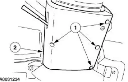
2. Remove the two steering wheel back cover plugs.
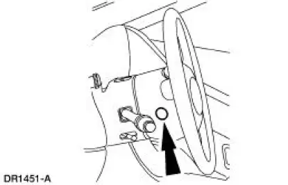
3. Remove the two driver air bag module retaining bolts.
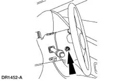
4. Remove the driver air bag module.
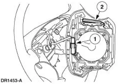
1. Disconnect the driver air bag module electrical connector.
2. Remove the driver air bag module.
5. NOTE: Make sure the wheels (1007) are in the straight-ahead position.
Remove the steering wheel (3600). For additional information, refer to Section.
6. Apply two strips of masking tape across the clockspring (14A664) to prevent accidental rotation when the clockspring is removed.
7. Remove the lower steering column shroud (3530).
1. Remove the tilt wheel handle and shank (3F609).
2. Remove the four screws.
3. Remove the lower steering column shroud.
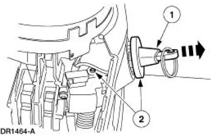
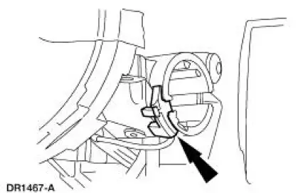
8. Remove the ignition switch lock cylinder (11582).
1. Position the ignition switch lock cylinder to the RUN position.
2. Using the suitable tool, push upward on the cylinder release tab while pulling the ignition switch lock cylinder outward.
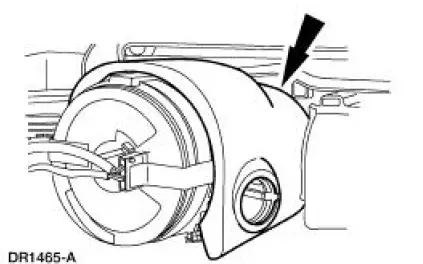
9. Raise the upper steering column shroud.
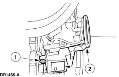
10. Remove the passive anti-theft system (PATS) transmitter.
1. Remove the PATS transmitter retaining screw.
2. Position the PATS transmitter out of the way.
11. Remove the key-in-ignition warning indicator switch.
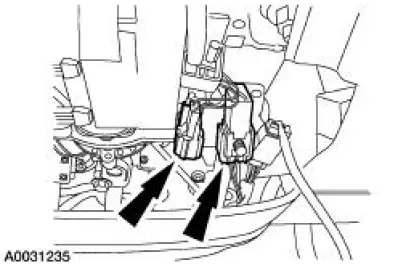
12. Remove the two clockspring electrical connectors from the bracket. Disconnect the remaining electrical connector.
13. Remove the wire harness from its holders.
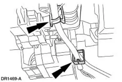
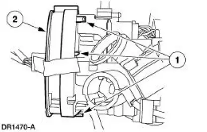
14. Remove the clockspring.
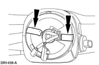
1. Pry the clockspring retaining clips loose.
2. Remove the clockspring.
 Clockspring
Special Tool(s)
Diagnostic Tool, Restraint
System (2 Req'd)
418-F088 (105-R0012)
...
 Installation
WARNING: To reduce the risk of serious personal injury, read
and follow all warnings,
cautions and notes at the beginning of the removal procedure.
Vehicles receiving a new clockspring
1. NOT ...
Other materials:
Installation
CAUTION: The upper suspension arm and bushing nuts must be tightened
with the
suspension at curb height. Failure to do so can result in bushing failure,
resulting in poor ride
and handling.
NOTE: If installing a new upper suspension arm and bushing, mark the ...
Drive Pinion Flange and Drive Pinion Seal
Special Tool(s)
2-Jaw Puller
205-D072 (D97L-4221-A) or
equivalent
Holding Fixture, Drive Pinion
Flange
205-126 (T78P-4851-A)
Installer, Drive Pinion Flange
205-002 (TOOL-4858-E) or
equivalent
...
Inspection and Verification
Certain axle noise or vibration symptoms are also common to the engine,
transmission, wheel
bearings, tires, and other parts of the vehicle. For this reason, be sure that
the cause of the trouble is
in the axle before disassembling, adjusting or repairing th ...
