Ford Mustang (1999-2004) Service Manual: Removal
1. Remove the differential assembly from the differential housing. For additional information, refer to Differential Case in this section.
2. CAUTION: Record the torque necessary to maintain rotation of the drive pinion gear through several revolutions prior to removing the pinion flange (4851).
Remove the pinion flange. For additional information, refer to Drive Pinion Flange and Drive Pinion Seal in this section.
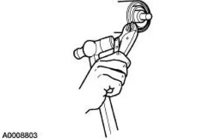
3. Force the rear axle drive pinion seal metal flange up. Install gripping pliers and strike with a hammer to remove the seal.
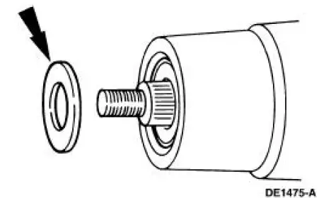
4. Remove the rear axle drive pinion shaft oil slinger (4670).
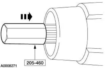
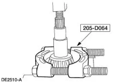
5. Using the special tool and a soft-faced hammer, drive the pinion assembly out of the outer differential pinion bearing (4621) and remove the drive pinion through the rear of the differential housing (4010).
6. Remove the outer differential pinion bearing.
7. Remove and discard the collapsible spacer (4662).
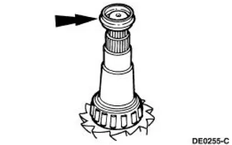
8. Using the special tool and a suitable press, remove the inner differential pinion bearing (4630).
9. NOTE: Do not remove the pinion bearing cups from the differential housing unless the cups are damaged.
Using the special tools, remove the outer differential drive pinion bearing cup (4616).
10. Using the special tools, remove the inner rear axle pinion bearing cup (4628).
 Drive Pinion
Special Tool(s)
Adapter for 205-S127
205-105 (T76P-4020-A3)
Adapter for 205-S127
205-109 (T76P-4020-A9)
Adapter for 205-S127
205-110 (T76P-4020-A10)
Adapter fo ...
 Installation
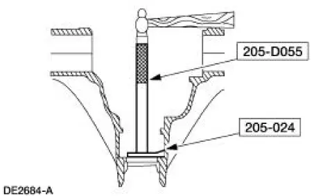
Using special tool 205-024
NOTE: This is the preferred method for installing the pinion bearing
cups. If necessary, proceed to
Using special tools 205-153, 205-024, 205-231, and 205-D055 in this proc ...
Other materials:
Getting assistance outside the U.S. And Canada
Before exporting your vehicle to a foreign country, contact the
appropriate foreign embassy or consulate. These officials can inform you
of local vehicle registration regulations and where to find unleaded fuel.
If you cannot find unleaded fuel or can only ge ...
Lamp Assembly - Fog Lamp (GT)
Removal
1. Raise and support the vehicle.
2. Remove the screw.
3. Partially lower the vehicle and remove the fog lamp assembly.
1. Disconnect the electrical connector.
2. Remove the two screws.
3. Remove the fog lamp assembly and replace the bul ...
Installation
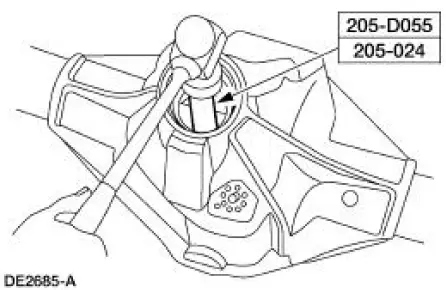
Using special tool 205-024
NOTE: This is the preferred method for installing the pinion bearing
cups. If necessary, proceed to
Using special tools 205-153, 205-024, 205-231, and 205-D055 in this procedure
for an alternate
method.
1. Position the special too ...
