Ford Mustang (1999-2004) Service Manual: Removal
1. Disconnect the battery negative cable.
2. Drain the engine cooling system.
3. Remove the RH exhaust manifold. For additional information, refer to Exhaust Manifold RH in this section.
4. Remove the lower intake manifold. For additional information, refer to Lower Intake Manifold in this section.
5. Remove the push rods. For additional information, refer to Push Rod in this section.
6. Remove the drive belt.
7. Disconnect the A/C manifold and tube assembly.
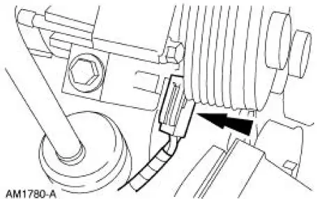
8. Disconnect the A/C compressor clutch electrical connector.
9. Remove the A/C compressor bracket.
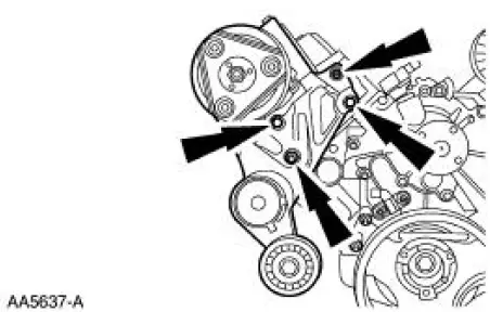
10. Remove the three exhaust manifold studs.
11. NOTE: Discard the cylinder head gasket.
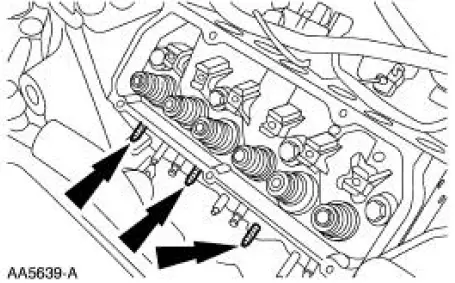
NOTE: Record the location of the long bolts and the short bolts.
Remove the cylinder head. Discard the cylinder head bolts.
 Cylinder Head RH
Material
...
 Installation
NOTE: Do not use a fiber disc to clean the surfaces. Fibers from
the disc can get into the oil pan and
oil and clog the oil bypass valve.
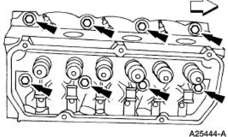
1. Clean and inspect the cylinder head for flatness.
2. ...
Other materials:
Engine oil check
Note: Check the level before starting the engine.
Note: Make sure that the level is between the MIN and MAX marks.
1. Make sure that your vehicle is on level ground.
2. Turn the engine off and wait 10 minutes for the oil to drain into the
oil pan.
3. Remove ...
Switch - Door Lock
Removal
1. CAUTION: Place a rag between the window regulator switch
plate and the door trim
panel to avoid damaging the door trim panel.
Position the window regulator switch plate (14524) aside.
1. Pull at service notch.
2. Lift to release t ...
Axle Housing Bushing
Special Tool(s)
Axle Suspension Bushing Set
204-S030 (T78P-5638-A)
Removal
CAUTION: Suspension fasteners are critical parts because they affect
performance of vital
components and systems and their failure can result in major service expense. ...
