Ford Mustang (1999-2004) Service Manual: Installation
NOTE: Do not use a fiber disc to clean the surfaces. Fibers from the disc can get into the oil pan and oil and clog the oil bypass valve.
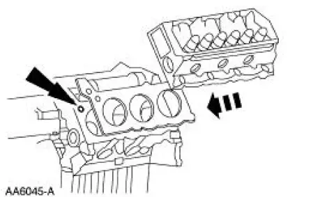
1. Clean and inspect the cylinder head for flatness. 2. Install a new head gasket on the cylinder block with the small hole to the front of the engine and position the cylinder head.
3. CAUTION: Always use new bolts.
NOTE: Lubricate the bolts with clean engine oil.
Install new bolts. Refer to the location note made during removal and make sure the bolts are installed the correct location.
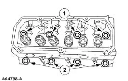
1. Install the new long bolts.
2. Install the new short bolts.
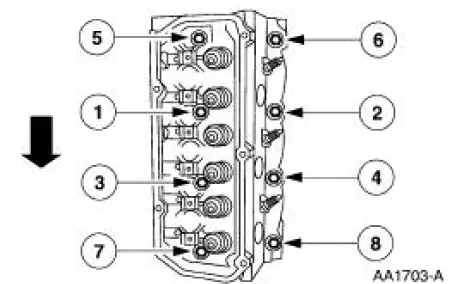
4. Tighten the bolts in three stages in the sequence shown.
- Stage 1: Tighten to 20 Nm (15 lb-ft).
- Stage 2: Tighten to 40 Nm (30 lb-ft).
- Stage 3: Tighten to 50 Nm (37 lb-ft).
5. CAUTION: Do not loosen all of the bolts at one time. Each bolt must be loosened and final-tightened prior to working on the next bolt in the sequence.
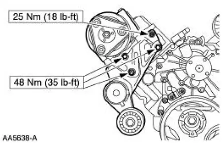
NOTE: The short bolts are numbered 2, 4, 6 and 8 and the long bolts are numbered 1, 3, 5 and 7.
Loosen, then tighten the bolts in the sequence shown:
- Tighten short bolts to 25 Nm (18 lb-ft), then tighten an additional 180 degrees.
- Tighten long bolts to 45 Nm (33 lb-ft), then tighten an additional 180 degrees.

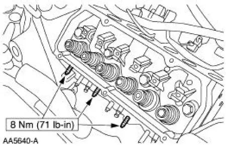
6. Install the three studs.
7. Install the bracket and bolts.
8. Connect the A/C compressor clutch electrical connector.
9. Connect the A/C manifold and tube assembly.
10. Install the accessory drive belt.
11. Install the push rods. For additional information, refer to Push Rod in this section.
12. Install the lower intake manifold. For additional information, refer to Lower Intake Manifold in this section.
13. Install the RH exhaust manifold. For additional information, refer to Exhaust Manifold RH in this section.
14. Connect the battery ground cable.
15. CAUTION: Correct cooling system bleeding is critical for correct engine cooling.
Fill and bleed the engine cooling system.
16. Recharge the A/C refrigerant system.
 Removal
1. Disconnect the battery negative cable.
2. Drain the engine cooling system.
3. Remove the RH exhaust manifold. For additional information, refer to Exhaust
Manifold RH in
this section.
4. Remo ...
 Oil Level Indicator and Tube
Removal and Installation
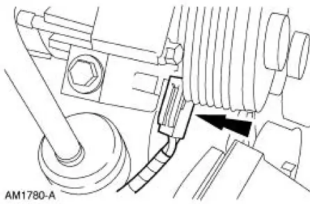
1. Remove the oil level indicator tube (6754).
Remove the bolt.
Remove the oil level indicator tube.
Remove and discard the oil level indicator tube O-ring.
2. To ...
Other materials:
Installation
1. Apply silicone gasket and sealant in the locations shown.
2. Install the engine front cover.
3. Install the belt idler pulleys and the bolts.
4. Connect the CMP sensor electrical connector.
5. Raise the vehicle.
6. Install the crankshaft fr ...
Refueling
WARNING: Fuel vapor burns violently and a fuel fire can cause
severe injuries. To help avoid injuries to you and others:
• Read and follow all the instructions on the pump island.
• Turn off your engine when you are refueling.
• Do not smoke if you are n ...
Evaporative Emission Repair Verification Drive Cycle
Special Tool(s)
Worldwide Diagnostic System
(WDS)
418-F224,
New Generation STAR (NGS)
Tester
418-F052, or equivalent scan
tool
Drive Cycle Recommendations
NOTE: The following procedure is designed to execute and
complete the evap ...
