Ford Mustang (1999-2004) Service Manual: Removal
WARNING: Do not smoke or carry lighted tobacco or open flame of any type when working on or near any fuel related components. Highly flammable mixtures are always present and can ignite. Failure to follow these instructions can result in personal injury.
1. With the vehicle in neutral, position it on a hoist. For additional information, refer to Section.
2. Disconnect the battery ground cable. For additional information, refer to Section.
3. Remove the upper intake manifold. For additional information, refer to Section..
4. Disconnect the following connectors:
- The 42 pin engine bulkhead electrical connector.
- The 16 pin electrical connector.
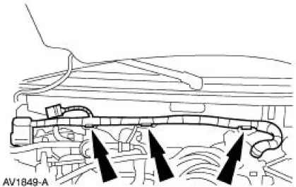
5. Separate the wiring harness from the dash panel.
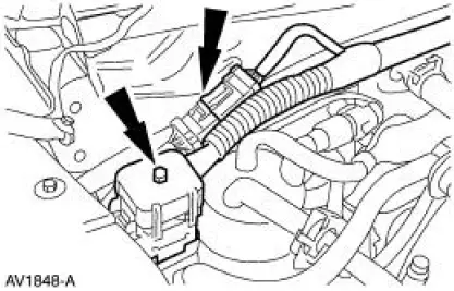
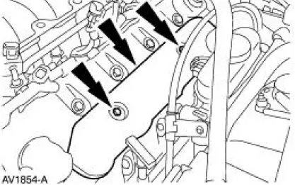
6. Remove the RH ignition coil cover.
- Remove the bolts.
- Remove the coil cover.
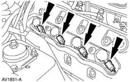
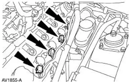
7. Disconnect the RH ignition coil electrical connectors.
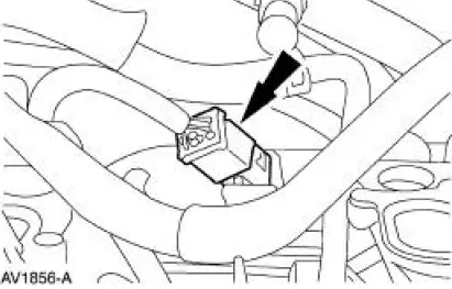
8. Disconnect the heated positive crankcase ventilation (PCV) valve electrical connector.
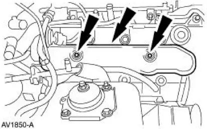
9. Remove the LH ignition coil cover.
- Remove the bolts.
- Remove the coil cover.
10. Disconnect the LH ignition coil electrical connectors.
11. Disconnect the transmission main control harness electrical connector.
12. Disconnect the engine control jumper harness electrical connector.
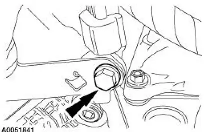
13. Remove the wiring harness bracket bolt.
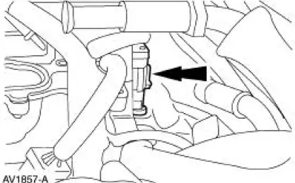
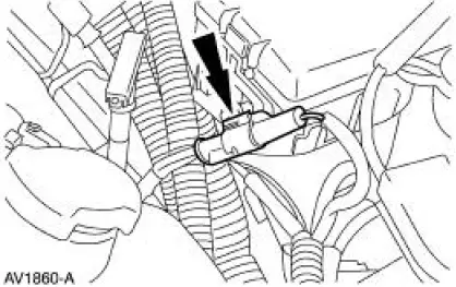
14. Disconnect the RH heated oxygen sensor (HO2S) electrical connector.
15. NOTE: LH side is shown, RH side is similar.
Disconnect the two radio ignition interference capacitor electrical connectors.
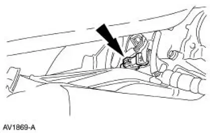
16. Disconnect the battery supply wire from the power distribution box stud.
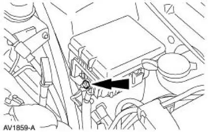
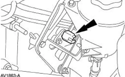
17. NOTE: The electrical connector is located under the power distribution box.
Disconnect the electrical connector.
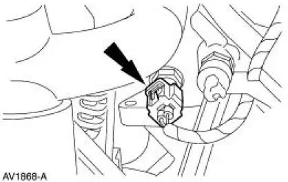
18. Disconnect the electrical connector.
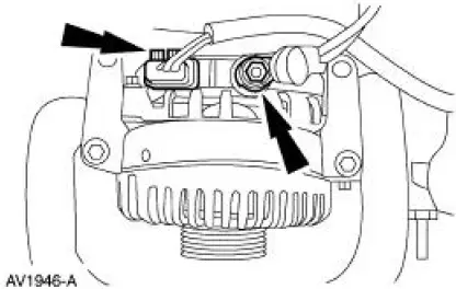
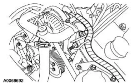
19. Disconnect the following generator electrical connectors:
- Battery power supply wire.
- Voltage regulator.
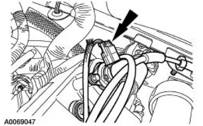
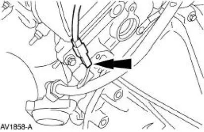
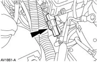
20. Disconnect the camshaft position (CMP) sensor electrical connector.
21. Disconnect the engine coolant temperature (ECT) sensor electrical connector.
22. Remove the wiring harness.
- Separate the wiring harness from the LH valve cover stud bolt.
- Separate the wiring harness from the power steering reservoir bracket.
 Wiring Harness
...
 Installation
1. Position the wiring harness:
Install the wiring harness retainer onto the LH valve cover stud bolt.
Install the wiring harness retainer into the power steering reservoir.
2. Connect the EC ...
Other materials:
Removal
Convertible
1. For removal of the back window glass, refer to Section.
Coupe
WARNING: To prevent glass splinters from entering eyes or
cutting hands, wear safety
glasses and heavy gloves when cutting glass from the vehicle.
2. Remove the roof side ...
Disassembly
1. NOTE: The index mark on the output shaft must be aligned with the
index mark on the output
shaft ring gear during the assembly procedure.
Remove the ring gear snap ring.
2. Separate the ring gear and output shaft.
3. Remove the three output shaft seal ...
Removal
WARNING: The restraints control module (RCM) orientation is critical
for proper system
operation. If a vehicle equipped with an air bag supplemental restraint system
(SRS) has been
involved in a collision in which the center tunnel area has been damaged,
in ...
