Ford Mustang (1999-2004) Service Manual: Installation
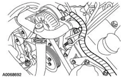
1. Position the wiring harness:
- Install the wiring harness retainer onto the LH valve cover stud bolt.
- Install the wiring harness retainer into the power steering reservoir.
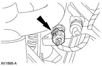
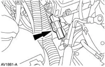
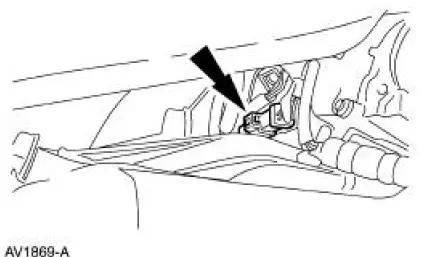
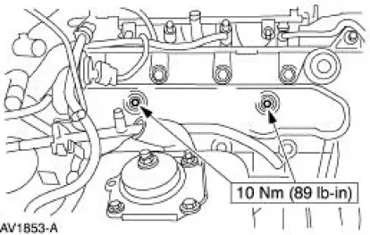
2. Connect the ECT sensor electrical connector.
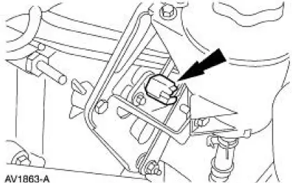
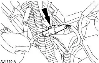
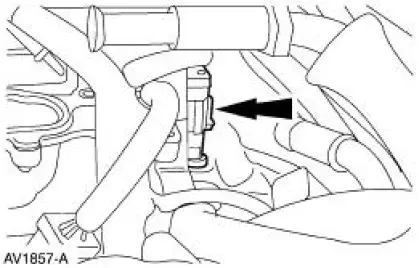
3. Connect the CMP sensor electrical connector.
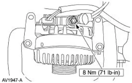
4. Connect the following generator electrical connectors:
- Battery power supply wire.
- Voltage regulator.
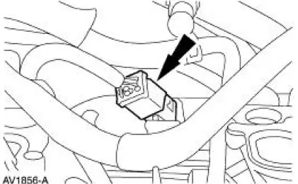
5. Connect the electrical connector.
6. Connect the electrical connector.
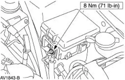
7. Install the battery supply wire to the power distribution box stud.
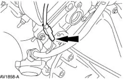
8. NOTE: LH side is shown, RH side is similar.
Connect the two radio ignition interference capacitor electrical connectors.
9. Connect the RH HO2S electrical connector.
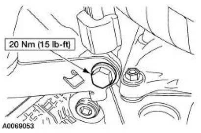
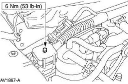
10. Install the wiring harness bracket bolt.
11. Connect the engine control jumper harness electrical connector.
12. Connect the transmission main control harness electrical connector.
13. Connect the LH ignition coil electrical connectors.
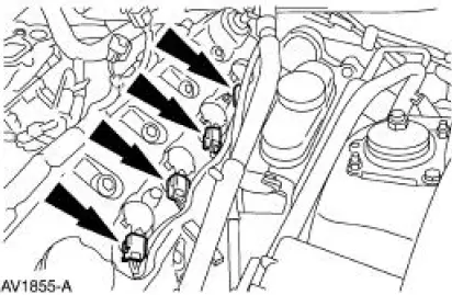
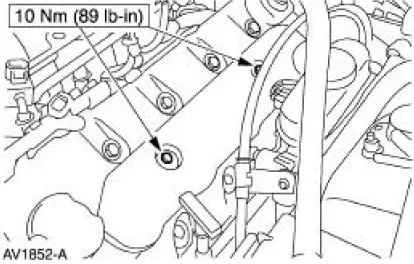
14. Install the LH ignition coil cover and bolts.
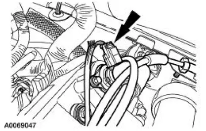
15. Connect the heated positive crankcase ventilation (PCV) vlave electrical connector.
16. Connect the RH ignition coil electrical connectors.
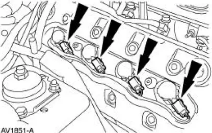
17. Install the RH ignition coil cover and bolts.
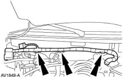
18. Install the wiring harness retainers into the dash panel.
19. Connect the following connectors:
- The 42 pin engine bulkhead electrical connector.
- The 16 pin electrical connector.
20. Install the upper intake manifold. For additional information, refer to Section.
21. NOTE: When the battery is disconnected and reconnected, some abnormal drive symptoms may occur while the vehicle relearns its adaptive strategy. The vehicle may need to be driven 16 km (10 mi) or more to relearn the strategy.
Connect the battery ground cable. For additional information, refer to Section.
 Removal
WARNING: Do not smoke or carry lighted tobacco or open flame of any
type when
working on or near any fuel related components. Highly flammable mixtures are
always present
and can ignite. Failure to ...
 Supply Manifold
Removal
WARNING: Do not smoke or carry lighted tobacco or open flame of any
type when
working on or near any fuel related components. Highly flammable mixtures are
always present
and can ignite. Fai ...
Other materials:
Manual seats
WARNING: Do not adjust the driver’s seat or seatback while the
vehicle is moving.
WARNING: Rock the seat backwards and forwards after
releasing the lever to make sure that it is fully engaged.
Moving the seats backward and
forward
Recline adjustment
WARNIN ...
Master Cylinder - Hydro-Boost
Removal
1. Disconnect the fluid level sensor connector.
2. Disconnect the brake tubes.
3. Remove the brake master cylinder nuts.
4. Remove the brake master cylinder (2140).
Installation
1. To install, reverse the removal procedure.
Bleed the brak ...
Gearshift Lever and Boot
Material
Removal and Installation
1. Remove the gearshift lever knob.
2. Remove the console panel gearshift plate. Lift the gearshift lever boot
over the gearshift lever.
3. Remove the bolts and the shift lever.
4. Remove the screws and the inner shif ...
