Ford Mustang (1999-2004) Service Manual: Spark Plugs
Special Tool(s)
 |
Remover, Spark Plug Wire 303-106 (T74P-6666A) |
Material
| Item | Specification |
| Silicone Brake Caliper Grease and Dielectric Compound D7AZ-19A331-A or equivalent | ESE-M1C171- A |
Removal and Installation
CAUTION: It is important to twist the spark plug wire boots while pulling upward to avoid possible damage to the spark plug wire.
CAUTION: Spark plug wires must be connected to the correct ignition coil terminal. Mark spark plug wire (12286) locations before removing them.
1. Remove the air cleaner outlet pipe. For additional information, refer to Section.
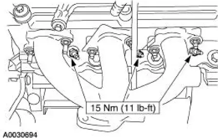
2. Using the special tool, remove the spark plug wires from the spark plugs using a twisting motion.
3. NOTE: Use compressed air to remove any foreign material from the spark plug well before removing the spark plugs.
NOTE: If an original spark plug is reused, make sure it is installed in the same cylinder from which it was taken. New spark plugs can be used in any cylinder.
NOTE: Left side shown, right side similar.
Remove the spark plugs.
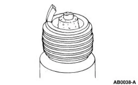
4. Inspect for gap bridged.
- This can be identified by deposit build up closing the gap between electrodes.
- This may be caused by oil or carbon fouling.
- Clean the spark plug.
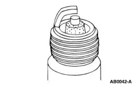
5. Inspect for oil fouling.
- This can be identified by wet black deposits on the insulator shell bore electrodes.
- This may be caused by excessive oil entering the combustion chamber through worn rings and pistons, excessive clearance between valve guides and stems, or worn or loose bearings. Correct the oil problem.
- Install a new spark plug.
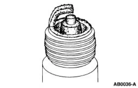
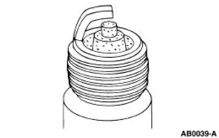
6. Inspect for carbon fouling.
- This can be identified by black, dry, fluffy carbon deposits on the insulator tips, exposed shell surfaces and electrodes.
- This may be caused by too cold a plug, dirty air cleaner, damaged fuel pump, too rich a fuel mixture or excessive idling.
- Clean the spark plug.
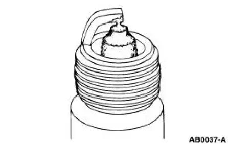
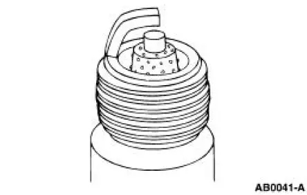
7. Inspect for normal burning.
- This can be identified by light tan or gray deposits on the firing tip.
8. Inspect for pre-ignition.
- This can be identified by melted electrodes and possibly a blistered insulator. Metallic deposits on the insulator indicate engine damage.
- Install a new spark plug.
9. Inspect for overheating.
- This can be identified by a white or light gray insulator with small black or gray brown spots and a bluish-burnt appearance of the electrodes.
- This may be caused by engine overheating, the wrong type of fuel, loose spark plugs, too hot a plug, low fuel pump pressure or incorrect ignition timing.
- Install a new spark plug.
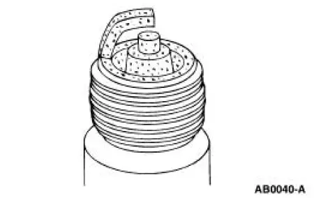
10. Inspect for fused spot deposits.
- This can be identified by melted or spotty deposits resembling bubbles or blisters.
- This can be caused by sudden acceleration.
- Clean the spark plug.
11. CAUTION: Be sure to orient the spark plug boots so the spark plug wires do not contact the exhaust manifold.
NOTE: Apply silicone brake caliper grease and dielectric compound to the inside of the spark plug wire boots.
To install, reverse the removal procedure.
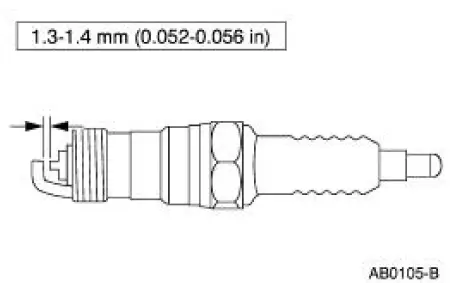
- Adjust the spark plug gap as necessary.
 Spark Plug Wire
Special Tool(s)
Remover, Spark Plug Wire
303-106 (T74P-6666A)
Material
Item
Specification
Silicone Brake Caliper Grease
and Dielectric Compound
D7AZ-19A331-A or equiva ...
 Engine Ignition - 4.6L (2V)
General Specifications
Torque Specifications
...
Other materials:
Door Window Glass Adjustment - Height Stop Adjustment
1. Close the front door.
2. Loosen the screws.
3. Raise the door window glass to the desired height.
4. Tighten the screws.
Door Window Glass Adjustment -Stabilizer
1. Raise the door window glass to the full up position.
2. Loosen the bolts.
3. ...
Installation
1. Install a new upper intake manifold gasket.
2. NOTE: Refer to the location note made during removal and make sure
the bolts are installed in
the correct locations.
Install the upper intake manifold. Tighten the bolts in two stages in the
sequence shown ...
Front Bumper Cover
Removal and Installation
NOTE: Mustang shown, GT and Cobra similar.
1. Remove the pin-type retainers and the radiator upper sight shield.
2. Remove the two pin-type retainers (one each side).
3. Remove the four front bumper cover nuts (two each side).
4. ...
