Ford Mustang (1999-2004) Service Manual: Steering Column Switches (Diagnosis and Testing)
Refer to Wiring Diagrams Cell 13 , Power Distribution for schematic and connector information.
Refer to Wiring Diagrams Cell 81 , Interval Wiper/Washer for schematic and connector information.
Refer to Wiring Diagrams Cell 85 , Headlamps for schematic and connector information.
Refer to Wiring Diagrams Cell 90 , Turn/Stop/Hazard Lamps for schematic and connector information.
Special Tool(s)
 |
Worldwide Diagnostic System (WDS) 418-F224, New Generation STAR (NGS) Tester 418-F052, or equivalent scan tool |
 |
73 Digital Multimeter 105-R0051 or equivalent |
Inspection and Verification
1. Verify the customer concern by operating the multifunction or ignition switch.
2. Visually inspect for obvious signs of mechanical and electrical damage.
Visual Inspection Chart
| Mechanical |
Electrical |
|
|
3. If the concern remains after the inspection, connect the scan tool to the data link connector (DLC) located beneath the instrument panel and select the vehicle to be tested from the scan tool menu. If the scan tool does not communicate with the vehicle:
- check that the program card is correctly installed.
- check the connections to the vehicle.
- check the ignition switch position.
4. If the scan tool still does not communicate with the vehicle, refer to the scan tool manual.
5. Carry out the DATA LINK DIAGNOSTIC TEST. If the scan tool responds with:
- CKT914, CKT915 or CKT70 =ALL ECUS NO RESP/NOT EQUIP
- NO RESP/NOT EQUIP for GEM, go to Pinpoint Test A.
- SYSTEM PASSED, retrieve and record the continuous diagnostic trouble codes (DTCs), erase the continuous DTCs and carry out self-test diagnostics for the GEM.
6. If the DTCs retrieved are related to the concern, go to the GEM Diagnostic Trouble Code (DTC) Index to continue diagnostics.
7. If no DTCs related to the concern are retrieved, proceed to the Symptom Chart to continue diagnostics.
GEM Diagnostic Trouble Code (DTC) Index
| DTC | Description | Source |
| B1217 | Horn Relay Coil Circuit Failure | GEM |
| B1218 | Horn Relay Coil Circuit Short to Vbatt | GEM |
| B1312 | Lamp Headlamp Input Circuit Short to Battery | GEM |
| B1317 | Battery Voltage High | GEM |
| B1318 | Battery Voltage Low | GEM |
| B1322 | Driver Door Ajar Circuit Short to Ground | GEM |
| B1330 | Passenger Door Ajar Circuit Short to Ground | GEM |
| B1334 | Decklid Ajar Rear Door Circuit Short to Ground | GEM |
| B1339 | Chime Input Request Circuit Short to Battery | GEM |
| B1340 | Chime Input Request Circuit Short to Ground | GEM |
| B1342 | ECU Is Defective | GEM |
| B1353 | Ignition Key-In Circuit Open | GEM |
| B1359 | Ignition Run/Acc Circuit Failure | GEM |
| B1396 | Power Door Lock Circuit Short to Battery | GEM |
| B1397 | Power Door Unlock Circuit Short to Battery | GEM |
| B1405 | Driver Power Window Down Circuit Short to Battery | GEM |
| B1408 | Driver Power Window Up Circuit Short to Battery | GEM |
| B1410 | Driver Power Window Motor Circuit Failure | GEM |
| B1426 | Lamp Safety Belt Circuit Short to Battery | GEM |
| B1428 | Lamp Safety Belt Circuit Failure | GEM |
| B1431 | Wiper Brake/Run Relay Circuit Failure | GEM |
| B1432 | Wiper Brake/Run Relay Circuit Short to Battery | GEM |
| B1434 | Wiper Hi/Low Speed Relay Coil Circuit Failure | GEM |
| B1436 | Wiper Hi/Low Speed Relay Coil Circuit Short to Battery | GEM |
| B1438 | Wiper Mode Select Switch Circuit Failure | GEM |
| B1441 | Wiper Mode Select Switch Circuit Short to Ground | GEM |
| B1446 | Wiper Park Sense Circuit Failure | GEM |
| B1448 | Wiper Park Sense Circuit Short to Battery | GEM |
| B1450 | Wiper Wash/Delay Switch Circuit Failure | GEM |
| B1453 | Wiper Wash/Delay Switch Circuit Short to Ground | GEM |
| B1458 | Wiper Washer Pump Motor Relay Circuit Failure | GEM |
| B1460 | Wiper Washer Pump Motor Relay Coil Circuit Short to Battery | GEM |
| B1462 | Safety Belt Switch Circuit Failure | GEM |
| B1466 | Wiper Hi/Low Speed Not Switching | GEM |
| B1473 | Wiper Low Speed Circuit Motor Failure | GEM |
| B1476 | Wiper High Speed Circuit Motor Failure | GEM |
| B1551 | Decklid Release Circuit Failure | GEM |
| B1553 | Decklid Release Circuit Short to Battery | GEM |
| B1555 | Ignition Run/Start Circuit Failure | GEM |
| B1687 | Lamp Dome Input Circuit Short to Battery | GEM |
| B2486 | LF Side Repeater Lamp Output Circuit Failure | GEM |
| B2488 | RF Side Repeater Lamp Output Circuit Failure | GEM |
| C1189 | Brake Fluid Level Sensor Input Short Circuit to Ground | GEM |
| C1223 | Lamp Brake Warning Output Circuit Failure | GEM |
| C1225 | Lamp Brake Warning Output Circuit Short to Battery | GEM |
Symptom Chart
| Condition | Possible Sources | Action |
|
|
|
|
|
|
|
|
|
|
|
|
|
|
|
|
|
|
Pinpoint Tests
PINPOINT TEST A: NO COMMUNICATION WITH THE GENERIC ELECTRONIC MODULE
| Test Step | Result / Action to Take |
| CAUTION: Use the correct probe adapter(s) when making measurements. Filaure to use the correct probe adapter(s) may damage the connector. | |
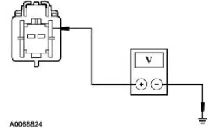
| A1 CHECK THE GENERIC ELECTRONIC MODULE (GEM) POWER SUPPLY | Yes GO to A2 . No REPAIR the circuit(s) in question. TEST the system for normal operation. |
|
|
| A2 CHECK THE GEM GROUND CIRCUIT 397 (BK/WH) FOR OPEN | Yes GO to A3 . No REPAIR the circuit(s) in question. TEST the system for normal operation. |
|
|
| A3 CHECK CIRCUIT 397 (BK/WH) FOR SHORT TO POWER | Yes REPAIR the circuit. TEST the system for normal operation. No |
|
|
PINPOINT TEST B: THE IGNITION SWITCH IS INOPERATIVE
| Test Step | Result / Action to Take |
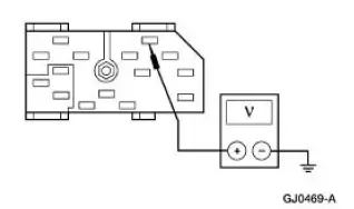
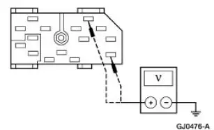
| B1 CHECK THE IGNITION SWITCH | Yes INSTALL a new BJB. TEST the system for normal operation. No INSTALL a new ignition switch. REFER to Ignition Switch . TEST the system for normal operation. |
|
PINPOINT TEST C: NO POWER IN ACC
| Test Step | Result / Action to Take |
| C1 CHECK THE RADIO FOR NORMAL OPERATION | Yes GO to C2 . No Go To Pinpoint Test D . |
|
|
| C2 CHECK THE VOLTAGE AT THE IGNITION SWITCH | Yes INSTALL a new ignition switch. REFER to Ignition Switch . TEST the system for normal operation. No REPAIR the circuit. TEST the system for normal operation. |
|
PINPOINT TEST D: NO POWER IN RUN
| Test Step | Result / Action to Take |
| D1 CHECK THE IGNITION SWITCH | Yes INSTALL a new BJB. TEST the system for normal operation. No INSTALL a new ignition switch. REFER to Ignition Switch . TEST the system for normal operation. |
|
PINPOINT TEST E: NO POWER IN START
| Test Step | Result / Action to Take |
| E1 CHECK THE VOLTAGE TO THE IGNITION SWITCH | Yes GO to E2 . No REPAIR the circuit in question.TEST system for normal operation. |
|
|
| E2 CHECK THE CONTINUITY OF THE IGNITION SWITCH | Yes GO to E3 . No INSTALL a new ignition switch. REFER to Ignition Switch . TEST the system for normal operation. |
|
|
| E3 CHECK CIRCUIT 16 (RD/LB), AND CIRCUIT 33 (WH/PK) | Yes REPAIR Circuit 16 (RD/LB). TEST the system for normal operation. No REPAIR Circuit 33 (WH/PK). TEST the system for normal operation. |
|
Component Test
Ignition Switch Continuity Check
Refer to Wiring Diagrams Cell 149, Component Testing.
Multifunction Switch
Refer to Wiring Diagrams Cell 149, Component Testing.
 Steering Column Switches
Torque Specifications
Steering Column Switches (DESCRIPTION AND OPERATION)
The steering column switches system consists of the following components:
multifunction switch (13K359)
key release butto ...
 Multifunction Switch
Removal
1. Disconnect the battery ground cable.
2. Remove the ignition switch lock cylinder.
1. Insert the ignition key into the ignition switch lock cylinder and
turn to RUN position.
2. ...
Other materials:
Transmission (DISASSEMBLY)
Special Tool(s)
Slide Hammer
100-001 (T50T-100-A)
Holding Fixture, Transmission
307-003 (T57L-500-B)
Slide Hammer
307-005 (T59L-100-B)
Remover, Transmission Fluid
Seal
307-048 (T74P-77248-A)
...
Removal
All vehicles
1. Remove the air intake scoop bracket. For additional information, refer to
Section.
2. Remove the RH valve cover. For additional information, refer to Valve Cover
RH in this section.
3. Remove the Hydro-Boost brake booster. For additional in ...
Cable Adjustment
1. NOTE: Make sure that the range selector lever is tight
against the rearward overdrive stop.
Place the transmission range selector lever in the overdrive
position.
2. Raise and support the vehicle. For additional information, refer
to Section.
...
