Ford Mustang (1999-2004) Service Manual: Removal
All vehicles
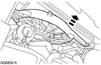
1. Remove the air intake scoop bracket. For additional information, refer to Section.
2. Remove the RH valve cover. For additional information, refer to Valve Cover RH in this section.
3. Remove the Hydro-Boost brake booster. For additional information, refer to Section.
Manual transmission vehicles
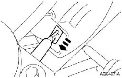
4. Remove the two clutch release cable retaining screws.
All vehicles
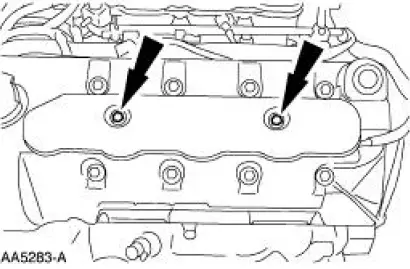
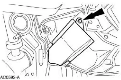
5. Remove the LH ignition coil cover bolts and the cover.
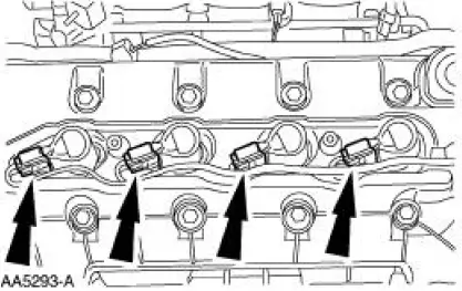
6. Disconnect the ignition coil electrical connectors.
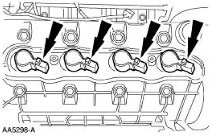
7. Remove the ignition coils.
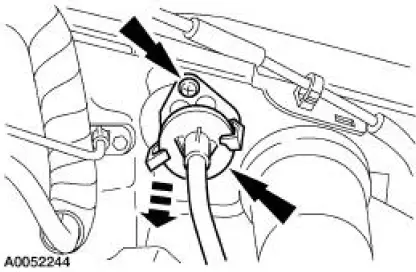
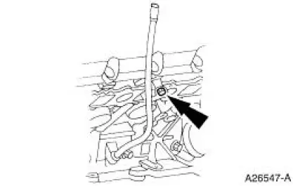
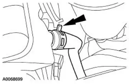
8. Remove the bolt and position the oil level indicator tube aside.
9. Remove the positive crankcase ventilation (PCV) valve hose and disconnect the electrical connector.
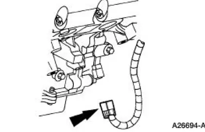
10. Disconnect the wiring harness anchor from the valve cover.
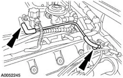
11. Remove the degas bottle vent hose.
12. Remove the degas bottle return hose.
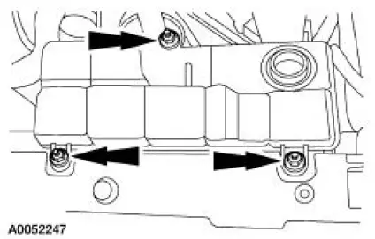
13. Remove the nuts and the degas bottle.
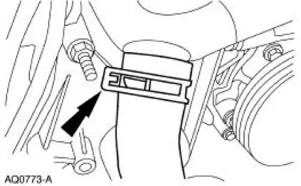
14. Disconnect the upper radiator hose from the bypass tube.
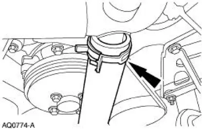
15. Disconnect the lower radiator hose from the bypass tube.
16. Disconnect the cooling fan electrical connector.
17. Separate the cooling fan wiring harness from the fan shroud.
18. Remove the LH cooling fan shroud bolt.
19. Remove the RH cooling fan shroud bolt.
20. Remove the cooling fan and shroud as an assembly.
21. Remove the crankshaft front oil seal. For additional information, refer to Crankshaft Front Oil Seal .
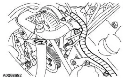
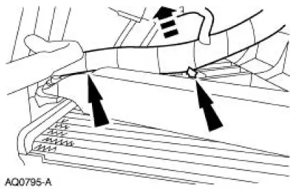
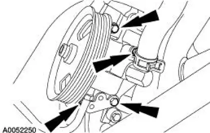
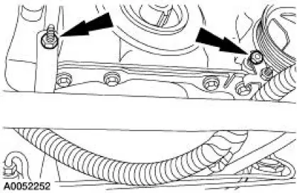
22. Remove the three bolts shown. Loosen the fourth bolt (hidden behind the p/s tube). Position the power steering pump aside.
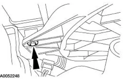
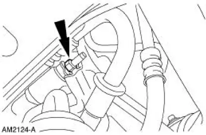
23. Remove the A/C muffler bracket nut.
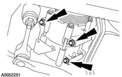
24. Remove the bolts and position the A/C compressor aside.
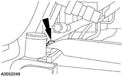
25. Disconnect the crankshaft position (CKP) sensor electrical connector.
26. Remove the wiring harness nuts and position the wiring harness aside.
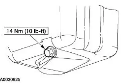
27. Remove the drain plug and drain the oil.
- Install the drain plug when finished.
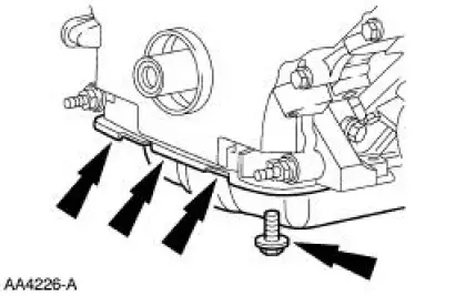
28. Remove the front four oil pan bolts.
Manual transmission vehicles
29. Remove the bolt and the clutch release cable shield.
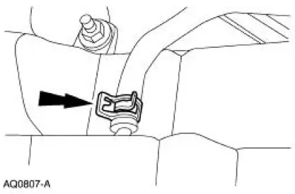
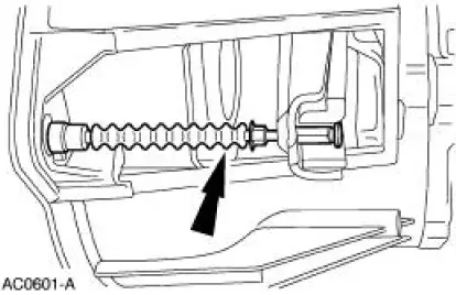
30. Disengage the clutch release cable from the clutch release fork.
31. Lower the vehicle.
All vehicles
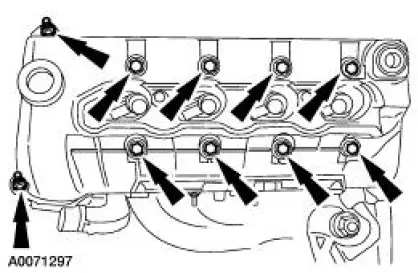
32. Remove the LH valve cover.
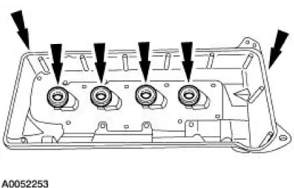
33. CAUTION: Do not use metal scraper, wire brushes, power abrasive discs or other abrasive means to clean the sealing surfaces. These tools cause scratches and gouges which make leak paths. Use a plastic scraping tool to remove all traces of old sealant.
Clean and inspect sealing surfaces and valve cover gaskets. If necessary, install new gaskets.
Make sure the gaskets are correctly seated on the valve cover.
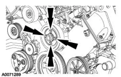
34. Remove the four bolts and the coolant pump pulley.
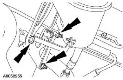
35. Remove the three bolts and position the power steering reservoir and bracket assembly aside.
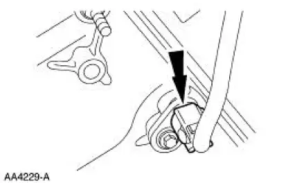
36. Disconnect the camshaft position (CMP) sensor electrical connector.
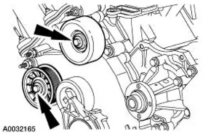
37. Remove the idler pulleys.
38. Remove the bolts and the studs and remove the engine front cover.
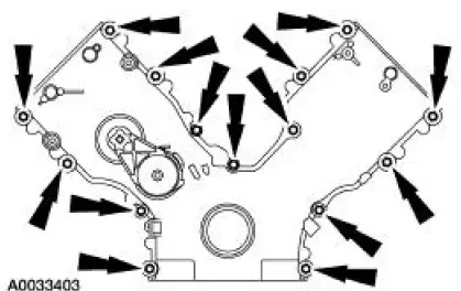
39. CAUTION: Do not use metal scrapers, wire brushes, power abrasive discs or other abrasive means to clean the sealing surfaces. These tools cause scratches and gouges which make leak paths. Use a plastic scraping tool to remove all traces of old sealant.
Remove and discard the gasket. Clean and inspect the sealing surfaces.
 Engine Front Cover
Material
Item
Specification
Metal Surface Cleaner
F4AZ-19A536-RA or equivalent
WSE-M5B392-
A
Silicone Gasket and Sealant
F7AZ-19554-EA or equivalent
WSE-M4G323-
A4
...
 Installation
All vehicles
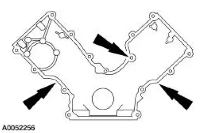
1. Position the engine front cover gasket on the engine front cover.
2. NOTE: If the engine front cover is not secured within four minutes, the
sealant must be removed
and the sealing ...
Other materials:
Climate Control System (Description and Operation)
WARNING: To avoid accidental deployment and possible injury, the air
bag system
backup power supply must be depleted before repairing any climate control
components. To
deplete the backup power supply, disconnect the battery ground cable and wait
one minute ...
Fuel Charging And Controls
The fuel injection supply manifold (9F792):
delivers fuel to the fuel injector.
receives fuel from the fuel supply line.
The throttle body (9E926):
controls air supply to the upper intake manifold (9424) by positioning
the throttle plate.
connects the ...
SYNC®
SYNC is an in-vehicle communications system that works with your
Bluetooth-enabled cellular phone and portable media player. This allows
you to:
• Make and receive calls.
• Access and play music from your portable music player.
• Use 911 Assist, Vehicle ...
