Ford Mustang (1999-2004) Service Manual: Steering Column Switches
Torque Specifications
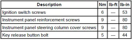
Steering Column Switches (DESCRIPTION AND OPERATION)
The steering column switches system consists of the following components:
- multifunction switch (13K359)
- key release button (manual transmission only) (3F527)
- ignition switch (11572)
The integrated multifunction switch is mounted to the LH side of the steering column and controls the turn signals, hazard flasher, windshield wiper/washer control, and headlamp dimmer/flash-to-pass.
The key release button is equipped with manual transmissions only.
The ignition switch is mounted below the steering column and is activated by rotating the key lock cylinder on the steering column.
- Steering Column Switches (Diagnosis and Testing)
- Multifunction Switch
- Ignition Switch
- Key Release Button
 Assembly
1. Install the locking lever cam and pin.
2. Install the lock actuator lever and pin.
3. Install the lock actuator lever return spring.
4. Install the ignition lock cylinder lockout lever.
5. ...
 Steering Column Switches (Diagnosis and Testing)
Refer to Wiring Diagrams Cell 13 , Power Distribution for schematic and
connector information.
Refer to Wiring Diagrams Cell 81 , Interval Wiper/Washer for schematic and
connector information.
Refer ...
Other materials:
Removal
1. Disconnect the electrical connectors from the EGR vacuum regulator
solenoid, the
supercharger bypass vacuum solenoid, and the differential pressure
feedback EGR system.
2. Disconnect the vacuum hoses from the differential pressure feedback EGR
sy ...
Transmission Case
Special Tool(s)
Handle
205-D055 (D81L-4000-A)
Installer, Bearing Cup
204-039 (T77F-1217-B)
Installer, Drive Pinion Bearing
Cup
205-054 (T71P-4616-A)
Installer, Rear Axle Oil Seal
205-155 (T80T-4000-Y)
...
Mass Air Flow (MAF) Sensor - 4.6L (2V)
Removal
CAUTION: The mass air flow (MAF) sensor hot wire sensing
element and housing are
calibrated as a unit and must be repaired as a complete assembly. Do not
damage the sensing
element (internal to housing) or possible failure to the mass air f ...
