Ford Mustang (1999-2004) Service Manual: Supercharger Cooling System Flushing
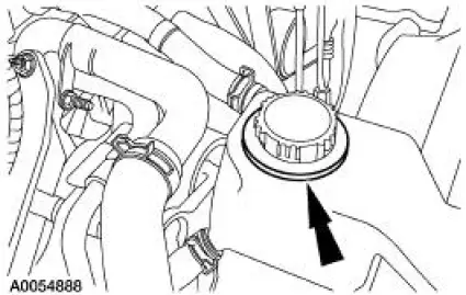
1. WARNING: Never remove the pressure relief cap while the engine is operating or when the cooling system is hot. Failure to follow these instructions can result in damage to the cooling system or engine or personal injury. To avoid having scalding hot coolant or steam blow out of the degas bottle when removing the pressure relief cap, wait until the engine has cooled, then wrap a thick cloth around the pressure relief cap and turn it slowly. Step back while the pressure is released from the cooling system. when you are sure all the pressure has been released, (still with a cloth) turn and remove the pressure relief cap.
Once pressure is released, remove the pressure relief cap.
2. Drain the cooling system. For additional information, refer to Supercharger Cooling System Draining, Filling and Bleeding in this section.
3. NOTE: Refer to the cooling system flusher manufacturer's operating instructions for specific vehicle hook-up.
Using an appropriate cooling system flusher, flush the intercooler cooling system.
Use Premium Cooling System Flush VC-1 meeting Ford specification ESR-M14P7-A.
4. Fill the cooling system. For additional information, refer to Supercharger Cooling System Draining, Filling and Bleeding in this section.
 Supercharger Cooling System Draining, Filling and
Bleeding
Supercharger Cooling System Draining, Filling and
Bleeding
Draining
WARNING: Never remove the pressure relief cap while the engine is
operating or when the
cooling system is hot. Failure to follow these instructions can result in damage
to the cooling
syste ...
 Water Pump
Removal and Installation
1. Disconnect the battery ground cable.
2. Drain the coolant. For additional information, refer to Supercharger Cooling
System Draining,
Filling and Bleeding in this section ...
Other materials:
Digital Transmission Range (TR) Sensor
Special Tool(s)
Alignment Gauge, TR Sensor
307-351 (T97L-70010-A)
Removal
1. Disconnect the battery ground cable. For additional information, refer
to Section.
2. Raise and support the vehicle. For additional information, refer to
Sectio ...
Installation
CAUTION: Electronic modules are sensitive to static electrical
charges. If exposed to
these charges, damage may result.
1. NOTE: Two technicians are necessary to carry out this step.
Install the instrument panel.
2. Install the upper instrument pa ...
Preliminary Inspection
The following items must be checked prior to beginning the diagnostic
procedures:
Know and Understand the Concern
In order to correctly diagnose a concern, first understand the
customer complaint or condition.
Customer contact may be required in ord ...
