Ford Mustang (1999-2004) Service Manual: Support Straps
Removal
WARNING: Do not smoke, carry lighted tobacco or an open flame of any type when working on or near any fuel-related components. Highly flammable mixtures are always present and may be ignited, possibly resulting in personal injury.
WARNING: Fuel supply lines on all vehicles equipped with fuel injected engines will remain pressurized for long periods of time after engine shutdown. Fuel system pressure must be relieved prior to fuel system service to prevent possible personal injury or a fire hazard.
1. Remove the fuel tank. For additional information, refer to Fuel Tank in this section.
2. Slide the strap and the retaining pin into the recess and remove the strap retaining pin.
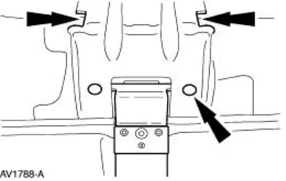
3. Remove the strap.
Installation
1. To install, reverse the removal procedure.
 Installation
1. CAUTION: Lubricate the filler pipe check valve area and the
tank-to-filler pipe
grommet with Serfactant prior to assembly or damage to the filler pipe check
valve will
occur.
NOTE: A new grommet ...
 Fuel Pump Module
Removal and Installation
1. Remove the fuel tank. For additional information, refer to Fuel Tank in
this section.
2. NOTE: For installation, tighten the bolts in the sequence shown.
Remove the modu ...
Other materials:
Window Glass - Quarter, Convertible
Removal
1. Remove the quarter trim panel. For additional information, refer
to Section.
2. Disconnect the connectors and remove the screw.
3. Remove the screw.
4. Remove the screw and the speaker.
5. Disconnect the electrical connector.
6. Remo ...
Cooling System Draining, Filling and Bleeding
Material
Item
Specification
Motorcraft Premium Gold
Engine Coolant
VC-7-A (in Oregon VC-7-B)
(yellow color)
WSS-M97B51-
A1
Draining
WARNING: Never remove the pressure relief cap while the engine is
operating or when the
cooling syst ...
911 Assist™
WARNING: Unless the 911 Assist setting is set on prior to a
crash, the system will not dial for help which could delay
response time, potentially increasing the risk of serious injury or death
after a crash.
WARNING: Do not wait for 911 Assist to make an emerg ...
