Ford Mustang (1999-2004) Service Manual: Differential Case and Ring Gear
Special Tool(s)
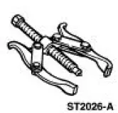 |
2-Jaw Puller 205-D072 (D97L-4221-A) or equivalent |
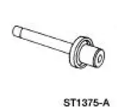 |
Installer, Differential Side Bearing 205-009 (T57L-4221-A1) |
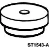 |
Step Plate 205-D016 (D80L-630-5) or equivalent |
 Axle Assembly
Removal and Installation
1. CAUTION: The vehicle must be on level ground and at curb height.
Mark the rear shock absorbers relative to their protective sleeve.
During installation, raise the suspen ...
 Disassembly
1. Remove the differential assembly from the differential housing. For
additional information, refer
to Differential Case in this section.
2. Remove the bolts.
3. CAUTION: Do not damage the thread ...
Other materials:
Driveshaft (Removal and Installation)
Material
Item
Specification
Threadlock and
Sealer
E0AZ-19554-AA
WSK-M2G351-A5 (type
II)
Removal and Installation
1. Raise and support the vehicle.
2. Carry out the following:
1. Place an index mark on the rear axle pinion flange and ...
On-board Diagnostics (OBD-II)
Your vehicle is equipped with a computer that monitors the engine’s
emission control system. This system is commonly known as the
on-board diagnostics system (OBD-II). The OBD-II system protects
the environment by ensuring that your vehicle continues to meet ...
Fuel Tank And Lines (Description and Operation)
WARNING: Do not smoke, carry lighted tobacco or an open flame of any
type when
working on or near any fuel-related component. Highly flammable mixtures are
always present
and may be ignited, possibly resulting in personal injury.
The vehicle utilizes a retur ...
