Ford Mustang (1999-2004) Service Manual: Switch - Exterior Rear View Mirror Control
Removal
1. CAUTION: Use a shop towel or similar material between the tool and the front door trim panel or damage to the front door trim panel may occur.
Position the window regulator switch plate aside.
1. Pull at service notch.
2. Lift to release the clip at the rear edge.
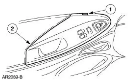
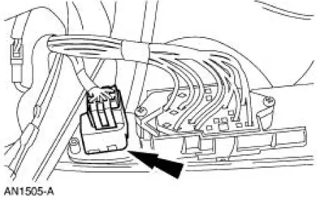
2. Remove the power exterior rear view mirror control switch.
- Disconnect the electrical connector.
Installation
1. To install, reverse the removal procedure.
 Mirror - Motor
Removal
1. Push in the upper edge of the mirror glass to the maximum travel.
2. Grasp the bottom of the mirror glass, pull outward and remove the mirror
glass.
3. Remove the mirror motor screws.
...
 Seating
Torque Specifications
...
Other materials:
Idle Air Control (IAC) Valve - 4.6L (2V)
Removal
1. Disconnect the battery ground cable. For additional information,
refer to Section.
2. NOTE: Discard the idle air control (IAC) valve gasket.
Remove the IAC valve.
Disconnect the connector.
Disconnect the hose.
Remove the bolts, ...
Engine (Installation)
Special Tool(s)
Lifting Bracket, Engine
303-D087 (D93P-6001-A1)
Lifting Bracket, Engine
303-D088 (D93P-6001-A2)
Installer Set, Teflon Seal
211-D027 (D90P-3517A) or
equivalent
Spreader Bar
303-D089 (D9 ...
Installation
1. Install the spring.
1. Position the spring and spring insulator in the front suspension lower
control arm.
2. Swing the arm into the fender well.
2. Position a jack stand under the front suspension lower control arm inboard
of the spring seat
and r ...
