Ford Mustang (1999-2004) Service Manual: Stoplamps
Refer to Wiring Diagrams Cell 90 , Turn/Stop/Hazard Lamps for schematic and connector information.
Special Tool(s)
 |
73III Automotive Meter or equivalent 105-R0057 |
Inspection and Verification
1. Verify the customer concerns.
2. Visually inspect for the following obvious signs of mechanical or electrical damage.
Visual Inspection Chart
| Mechanical |
Electrical |
|
|
3. If an obvious cause for an observed or reported concern is found, correct the cause (if possible) before proceeding to the next step.
4. If the concern is not visually evident, determine the symptom and refer to the Symptom Chart.
Symptom Chart
| Condition | Possible Sources | Action |
|
|
|
|
|
|
|
|
|
Pinpoint Tests
PINPOINT TEST G: THE STOPLAMPS ARE INOPERATIVE
| Test Step | Result / Action to Take |
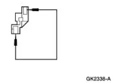
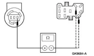
| G1 CHECK CIRCUIT 10 (LG/RD) FOR AN OPEN | Yes GO to G2 . No REPAIR the circuit. TEST the system for normal operation |
|
|
| G2 CHECK THE CIRCUIT 810 (RD/LG) FOR AN OPEN | Yes INSTALL a new BPP switch. REFER to Lamp Switch- Brake Pedal Position (BPP) in this section. TEST the system for normal operation. No REPAIR circuit 810 (RD/LG) or 569 (DG) as necessary. TEST the system for normal operation. |
|
PINPOINT TEST H: ONE OR MORE STOPLAMPS ARE INOPERATIVE
| Test Step | Result / Action to Take |
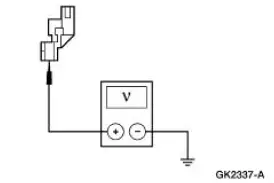
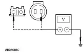
| H1 CHECK THE VOLTAGE TO THE INOPERATIVE STOPLAMP | Yes REPAIR circuit 1205 (BK). TEST the system for normal operation. No If high mounted stoplamp, REPAIR circuit 569 (DG). TEST the system for normal operation. If rear stoplamp, GO to H2 . |
|
|
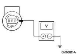
| H2 CHECK CIRCUIT 9 (LG/OG) OR 5 (OG/LB) FOR AN OPEN | Yes INSTALL a new multifunction switch. REFER to Section . TEST the system for normal operation. No REPAIR the circuit in question. TEST the system for normal operation. |
|
PINPOINT TEST I: THE STOPLAMPS ARE ON CONTINUOUSLY
| Test Step | Result / Action to Take |
| I1 CHECK THE BRAKE PEDAL POSITION (BPP) SWITCH | Yes GO to I2 . No INSTALL a new BPP switch. REFER to Lamp Switch- Brake Pedal Position (BPP) . TEST the system for normal operation. |
|
|
| I2 CHECK THE SPEED CONTROL SYSTEM | Yes GO to I3 . No REFER to Section. |
|
|
| I3 CHECK CIRCUIT 511 (LG) FOR SHORT TO POWER | Yes GO to I4 . No REPAIR the circuit. TEST the system for normal operation |
|
|
| I4 CHECK CIRCUIT 810 (LG/RD) FOR SHORT TO POWER | Yes GO to I5 . No REPAIR the circuit. TEST the system for normal operation |
|
|
| I5 CHECK THE MULTIFUNCTION SWITCH | Yes If the high mounted stoplamp is illuminated, REPAIR circuit 569 (DG) or 511 (LG) as necessary. TEST the system for normal operation. If only the LH stoplamp is illuminated, REPAIR circuit 9 (LG/OG). TEST the system for normal operation. If only the RH stoplamp is illuminated, REPAIR circuit 5 (OG/LB). TEST the system for normal operation. No INSTALL a new multifunction switch. REFER to Section. TEST the system for normal operation |
|
 Headlamps
Refer to Wiring Diagrams Cell 85 , Headlamps for schematic and
connector information.
Special Tool(s)
73III Automotive Meter or
equivalent
105-R0057
Inspection and Verification
...
 Turn Signal and Hazard Lamps
Refer to Wiring Diagrams Cell 90 , Turn/Stop/Hazard Lamps for schematic
and connector information.
Special Tool(s)
73 III Automotive Meter
105-R0057 or equivalent
Inspection and Ver ...
Other materials:
Ignition switch
A. Off: The ignition is off.
Note: When you switch the ignition off and leave your vehicle, do not
leave your key in the ignition. This could cause your vehicle battery to
lose charge.
B. Accessory: Allows the electrical accessories such as the radio to
ope ...
Rocker Arms - Inspection
CAUTION: Do not attempt to true surfaces by grinding. Check the
rocker arm pad, side
rails and seat for excessive wear, cracks, nicks or burrs. Check the rocker
arm seat bolt for
stripped or broken threads. Install new components as ncessary or possible ...
Trim Panel - Quarter, Coupe
Removal and Installation
1. Remove the upper quarter trim panel. For additional information,
refer to Trim Panel-Upper
Quarter in this section.
2. Remove the scuff plate.
3. Remove the pin-type retainers.
4. Lower the rear seat backrests.
5. Rem ...
