Ford Mustang (1999-2004) Service Manual: Switch - Horn
Removal
1. Remove the driver side air bag module (043B13). Refer to Section.
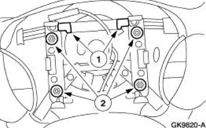
2. Remove the switches.
1. Disconnect the horn wire from the switches.
2. Remove the horn switch screws and remove the switches.
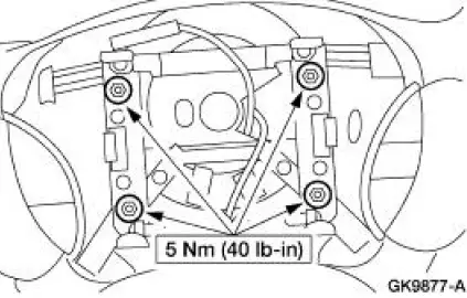
Installation
1. To install, reverse the removal procedure.
- Prove out the air bag system. Refer to Section.
 Horn (Diagnosis and Testing)
Refer to Wiring Diagrams Cell 44 , Horns/Cigar Lighter for schematic
and connector information.
Special Tool(s)
73 Digital Multimeter or
equivalent
105-R0051
Inspection and Veri ...
 Warning Devices
Warning Devices
The warning device system consists of the following components:
door ajar switches
generic electronic module (GEM)
key-in-ignition warning switch
safety belt switch
...
Other materials:
Degas Bottle - 4.6L(2V) and 4.6L(4V)
Removal and Installation
1. Drain the engine coolant from the degas bottle only. For additional
information, refer to Cooling
System Draining, Filling and Bleeding in this section.
2. Disconnect the radiator vent hose.
3. Remove the degas bottle return hos ...
Engine (Removal)
Special Tool(s)
Lifting Bracket Set, Engine
303-D095 (D94L-6001-A) or
equivalent
Spreader Bar
303-D089 (D93P-6001-A3) or
equivalent
Heavy Duty Floor Crane
014-00071 or equivalent
Removal
WARNING: Do not smoke or ...
Synchronizers
Disassembly and Assembly
NOTE: This procedure applies to all synchronizer assemblies.
1. NOTE: Synchronizer components are not interchangeable. During
disassembly, mark each
individual synchronizer for assembly. Synchronizer hubs and sleeves are a
selected a ...
