Ford Mustang (1999-2004) Service Manual: Horn (Diagnosis and Testing)
Refer to Wiring Diagrams Cell 44 , Horns/Cigar Lighter for schematic and connector information.
Special Tool(s)
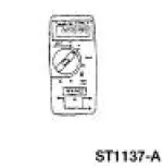 |
73 Digital Multimeter or equivalent 105-R0051 |
Inspection and Verification
1. Verify the customer concern by operating the horn (13832).
2. Visually inspect for obvious signs of mechanical and electrical damage.
Visual Inspection Chart
| Mechanical | Electrical |
|
|
3. If fault is not visually evident, determine the symptom and proceed to Symptom Chart.
Symptom Chart
| Condition | Possible Sources | Action |
|
|
|
|
|
|
Pinpoint Tests
PINPOINT TEST A: THE HORN DOES NOT SOUND
| Test Step | Result / Action to Take |
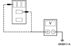
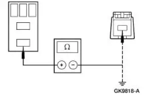
| A1 CHECK POWER SUPPLY TO HORN RELAY | Yes GO to A2 . No REPAIR the circuit in question. TEST the system for normal operation. |
|
|
| A2 CHECK HORN RELAY | Yes GO to A3 . No INSTALL a new horn relay. TEST the system for normal operation. |
|
|
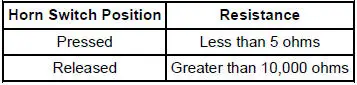
| A3 CHECK HORN SWITCH SIGNAL TO HORN RELAY | Yes GO to A4 . No GO to A5 . |
Horn Switch Position
|
|
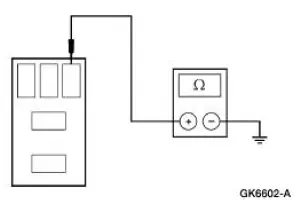
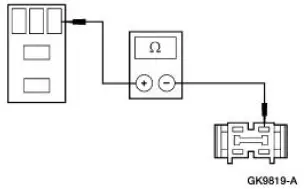
| A4 CHECK WIRE BETWEEN HORN RELAY AND HORN | Yes INSTALL new horns. TEST the system for normal operation. No REPAIR the circuit. TEST the system for normal operation. |
|
|
| A5 CHECK WIRE BETWEEN HORN RELAY AND AIR BAG SLIDING CONTACT | Yes GO to A6 . No REPAIR the circuit. TEST the system for normal operation. |
|
|
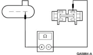
| A6 CHECK AIR BAG SLIDING CONTACT | Yes GO to A7 . No INSTALL a new air bag sliding contact. REFER to Section. TEST the system for normal operation. |
|
|
| A7 CHECK THE STEERING WHEEL SWITCH HARNESS | Yes INSTALL a new horn switch. REFER to Switch-Horn . TEST the system for normal operation. No INSTALL a new steering wheel switch harness. TEST the system for normal operation. |
|
PINPOINT TEST B: THE HORN SOUNDS CONTINUOUSLY
| Test Step | Result / Action to Take |
| B1 CHECK HORN CIRCUIT 1 (DB) | Yes REPAIR Circuit 1 (DB) for short to battery. TEST the system for normal operation. No GO to B2 . |
|
|
| B2 CHECK HORN RELAY | Yes REINSTALL the horn relay. GO to B3 . No INSTALL a new horn relay. TEST the system for normal operation. |
|
|
| B3 CHECK CIRCUIT 6 (YE/LG) | Yes GO to B4 . No RECONNECT the air bag sliding contact. GO to B5 . |
|
|
| B4 CHECK GEM INPUT | Yes REPAIR Circuit 6 (YE/LG). TEST the system for normal operation. No INSTALL a new GEM; REFER to Section. TEST the system for normal operation. |
|
|
| B5 CHECK THE AIR BAG SLIDING CONTACT | Yes INSTALL a new air bag sliding contact. REFER to Section. TEST the system for normal operation. No GO to B6 . |
|
|
| B6 CHECK STEERING WHEEL SWITCH HARNESS | Yes INSTALL a new horn switch. REFER to Switch- Horn . TEST the system for normal operation. No INSTALL a new steering wheel switch harness. TEST the system for normal operation. |
|
 Horn
Horn
Torque Specifications
Horn
The horn system consists of the following:
dual horns (one high-pitched, one low-pitched)
horn switch (located underneath the driver side air bag module
[043 ...
 Switch - Horn
Removal
1. Remove the driver side air bag module (043B13). Refer to Section.
2. Remove the switches.
1. Disconnect the horn wire from the switches.
2. Remove the horn switch screws and ...
Other materials:
Gear (Removal and Installation)
Special Tool(s)
Teflon Seal Replacer Set
211-D027 (D90P-3517-A) or
Equivalent
Tie Rod End Remover
211-001 (TOOL-3290-D)
Removal
1. Turn the steering wheel as necessary to position the wheels in the
straight-ahead position. Do
not loc ...
Emission control system
WARNING: Do not park, idle, or drive your vehicle in dry grass
or other dry ground cover. The emission system heats up the
engine compartment and exhaust system, which can start a fire.
WARNING: Exhaust leaks may result in entry of harmful and
potentially leth ...
Gauges
Type 1
Cluster shown in standard measure. Metric similar.
A. Speedometer
B. Fuel gauge
C. Engine coolant temperature gauge
D. Tachometer
E. Information display. See Information displays for more information.
Fuel Gauge
Indicates approximately how much fuel i ...
