Ford Mustang (1999-2004) Service Manual: Air Conditioning (Description and Operation)
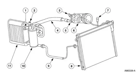
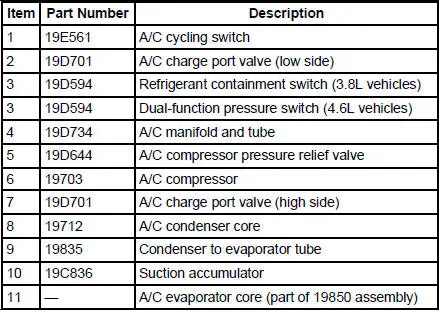
The A/C refrigerant system is a clutch cycling orifice tube type. The system components are:
- A/C compressor (19703)
- A/C clutch (2884)
- A/C condenser core (19712)
- A/C evaporator core (19860)
- suction accumulator (19C836)
- connecting refrigerant lines
The refrigeration system operation is controlled by the:
- A/C evaporator core orifice (19D990).
- A/C cycling switch (19E561).
- A/C compressor pressure relief valve (19D644).
- Refrigerant containment switch (3.8L) (19D594).
- Dual-function pressure switch (4.6L) (19D594).
The refrigerant system incorporates an A/C compressor controlled by an A/C cycling switch.
The A/C cycling switch senses A/C evaporator core pressure to control A/C compressor operation.
An A/C compressor pressure relief valve is installed in the A/C manifold and tube (19D734) to protect the refrigerant system against excessively high refrigerant pressures.
An evaporator core orifice is installed in the A/C evaporator core inlet tube to meter the liquid refrigerant into the A/C evaporator core.
A refrigerant containment switch is installed on 3.8L vehicles to cut-off A/C compressor operation in the event of abnormally high refrigerant system pressure.
A dual-function pressure switch is used on 4.6L vehicles for cooling fan control, and to cut-off A/C compressor operation in the event of abnormally high refrigerant system pressure.
Refrigeration System Components
- A/C Compressor and Clutch Assembly
- A/C Compressor Pressure Relief Valve
- Refrigerant Lines
- Evaporator Core Orifice
- Suction Accumulator
- Dual-Function Pressure Switch (4.6L)
- Spring Lock Coupling
 Air Conditioning
General Specifications
Torque Specifications
...
 A/C Compressor and Clutch Assembly
NOTE: Internal A/C compressor components are not serviced separately.
The FS-10 A/C compressor
is serviced only as an assembly. The A/C clutch pulley, A/C clutch field coil
(19D798) and the shaft
...
Other materials:
Child restraint and safety belt maintenance
Inspect the vehicle safety belts and child safety seat systems periodically
to
make sure they work properly and are not damaged. Inspect the vehicle
and child seat safety belts to make sure there are no nicks, tears or cuts.
Replace if necessary. All vehicle ...
Automatic Transaxle/Transmission
General Specifications
a - MERCON V is not interchangeable at this time with the current MERCON
fluids. Check the
transmission fluid level indicator to determine the correct fluid and refer to
the Workshop/Owner
publication to determine the correct service ...
Reporting safety defects (U.S. only)
If you believe that your vehicle has
a defect which could cause a crash
or could cause injury or death, you
should immediately inform the
National Highway Traffic Safety
Administration (NHTSA) in addition to notifying Ford Motor Company.
If NHTSA receives si ...
