Ford Mustang (1999-2004) Service Manual: Cylinder Head
Special Tool(s)
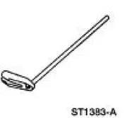 |
Compressor, Valve Spring 303-163 (T81P-6513-A) |
Material
| Item | Specification |
| SAE 5W-20 Premium Synthetic Blend Motor Oil XO-5W20-QSP or equivalent | WSS-M2C153- H |
Disassembly and Assembly
CAUTION: If the components are to be reinstalled, they must be installed in the same position. Mark the components removed for location.
1. Remove the spark plugs (12405) if necessary.
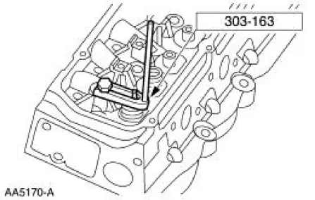
2. Using the special tool, compress the valve springs (6513).
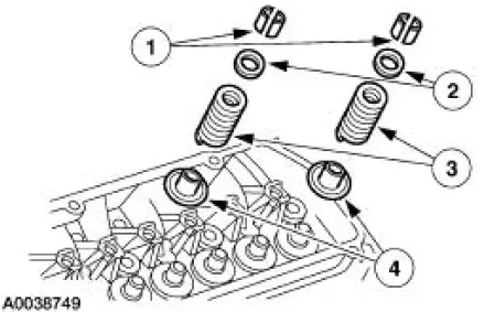
3. Remove the following:
1. The valve spring retainer key (6518).
2. The valve spring retainers (6514).
3. The valve springs (6513).
4. The valve stem seals and seats (6A517).
4. Inspect the components.
5. CAUTION: Lubricate the parts with clean engine oil before installing.
To assemble, reverse the disassembly procedure.
 Engine (Disassembly)
Special Tool(s)
Service Set, Camshaft
303-017 (T65L-6250-A)
Remover, Crankshaft Vibration
Damper
303-009 (T58P-6316-D)
Lifting Bracket Set, Engine
303-D095 ( ...
 Piston
Special Tool(s)
Piston Pin Tool or equivalent
303-D034 (D81L-6135-A)
Material
Item
Specification
SAE 5W-20 Premium Synthetic
Blend Motor Oil
XO-5W20-QSP or equivalent
...
Other materials:
Wheel Hub or Axle Flange Face Runout
NOTE: If the axle shaft assembly is removed, check runout of the shaft
itself. The forged (unmachined)
part of the shaft is allowed to have as much as 3.0 mm (0.120 inch) runout. This
alone will not cause a
vibration condition.
1. Position the special tool ...
Hydraulic Control Unit
Removal
1. Disconnect the battery ground cable(14301).
2. Disconnect the anti-lock-brake control module electrical connector.
3. NOTE: The 4 wheel anti-lock brake system (4WABS) with traction
control is shown , the
4WABS without traction control system is ...
Interior Lighting (Diagnosis and Testing)
Refer to Wiring Diagrams Cell 111 , Remote Control Alarm and Lock System
for schematic and
connector information.
Refer to Wiring Diagrams Cell 59 , Generic Electronic Module for schematic
and connector
information.
Refer to Wiring Diagrams Cell 89 , ...
