Ford Mustang (1999-2004) Service Manual: Evaporative Emissions (Description and Operation)
Component Location
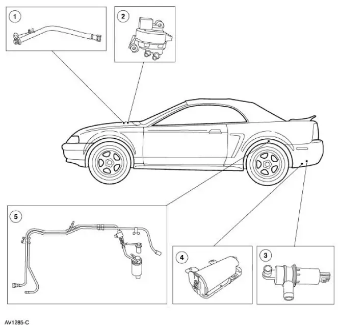
The evaporative emission system:
- is equipped with an on-board refueling vapor recovery (ORVR) system.
- prevents hydrocarbon emissions from reaching the atmosphere.
- stores fuel vapors in the evaporative emission (EVAP) canister that are generated during vehicle operation or hot soak, or vehicle refueling, until they can be consumed by the engine.
- routes the stored fuel vapors to the engine during engine operation.
- is controlled by the powertrain control module (PCM) which uses various sensor inputs to calculate the desired amount of purge flow. The PCM regulates the purge flow, induced by the application of intake manifold vacuum, by varying the duty cycle applied to the EVAP canister purge valve.
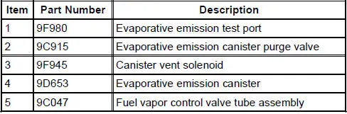
- has an evaporative emission test port for test purposes.
The fuel vapors are routed:
- from the fuel tank through the fuel vapor control valve and fuel vapor vent valve.
- to the EVAP canister through a vapor line.
- to the engine when the EVAP canister purge valve is opened by the PCM.
The fuel tank pressure (FTP) sensor:
- monitors the pressure levels in the fuel tank.
- communicates the pressure reading to the PCM during the OBDII leak test.
- is located in-line above the fuel tank and is serviced as part of the fuel vapor control valve tube assembly.
The evaporative emission canister:
- is located in the left rear quarter panel.
- contains activated carbon.
- stores fuel vapor.
The fuel tank filler cap:
- relieves system pressure above 14 kPa (56.21 inches H 2 O).
- relieves system vacuum below 3.8 kPa (15.26 inches H 2 O).
The canister vent solenoid:
- is normally open.
- seals the EVAP system for the inspection and maintenance (I/M 240) test and OBDII leak and pressure tests.
- is mounted to the evaporative emission canister.
- is repaired as a separate item.
The evaporative emission (EVAP) canister purge valve:
- is normally closed.
- regulates purging of the EVAP canister.
- is controlled by the PCM.
- is located in the right front inner fender well.
The fuel vapor control valve tube assembly:
- consists of the fuel vapor control valve, fuel vapor vent valve and an in-line fuel tank pressure sensor.
- prevents suspended liquid fuel from being drawn into the evaporative emission canister along with the fuel vapors.
- returns the liquid to the fuel tank.
- includes a fresh air transfer tube routing fresh air between the canister vent solenoid hose and the fuel tank filler pipe assembly.
- requires two grommets to seal the fuel vapor control valve and fuel vapor vent valve to the fuel tank.
The evaporative emission (EVAP) system monitor:
- is a self-test strategy within the PCM, which tests the integrity of the EVAP system.
- monitors the EVAP system for leaks.
- monitors electronic EVAP components for irrationally high or low voltages.
- monitors for correct EVAP system operation.
- utilizes intake manifold vacuum to test the EVAP system and involves several stages.
The evaporative emission (EVAP) test port:
- is used to connect the Evaporative Emission System Leak Tester to the EVAP system.
- is located on the EVAP canister purge outlet tube near the EVAP canister purge valve.
 Evaporative Emissions
General Specifications
Torque Specifications
...
 Evaporative Emissions (Diagnosis and Testing)
Special Tool(s)
Evaporative Emission System
Leak Tester
310-F007 (134-00056) or
equivalent
Worldwide Diagnostic System
(WDS)
418-F224,
New Generation STAR (NGS)
Te ...
Other materials:
Installation
1. Position the fuel charging wiring in the vehicle and attach to the rear of
the intake manifold.
2. NOTE: Make sure the locking clips are fully engaged into the bracket.
Reposition the accelerator cable and the speed control cable (if equipped)
and ...
Using snow chains
WARNING: Driving too fast for conditions creates the possibility
of loss of vehicle control. Driving at very high speeds for
extended periods of time may result in damage to vehicle components.
WARNING: Snow tires must be the same size, load index, speed
ratin ...
Pinion Seal
Special Tool(s)
Installer, Drive Pinion Oil Seal
205-133 (T79P-4676-A)
Removal
1. Remove the pinion flange (4851). For additional information, refer to
Drive Pinion Flange in this
section.
2. Force up the metal flange of the rear axle drive p ...
